Dehumidifying container

A container and container body technology, which is applied in the field of dehumidification containers, can solve the problems of plastic moisture, etc., and achieve the effect of improving efficiency and ensuring yield

Inactive Publication Date: 2009-06-10
HONG FU JIN PRECISION IND (SHENZHEN) CO LTD +1
View PDF0 Cites 1 Cited by
  • Summary
  • Abstract
  • Description
  • Claims
  • Application Information

AI Technical Summary

Problems solved by technology

[0004] Therefore, it is necessary to provide a dehumidification container to solve the problem of damp plastic in the hopper

Method used


Image

  • Dehumidifying container
  • Dehumidifying container
  • Dehumidifying container

Examples


Embodiment Construction

[0013] The dehumidification container provided by the technical solution will be further described in detail below with reference to the accompanying drawings and embodiments.

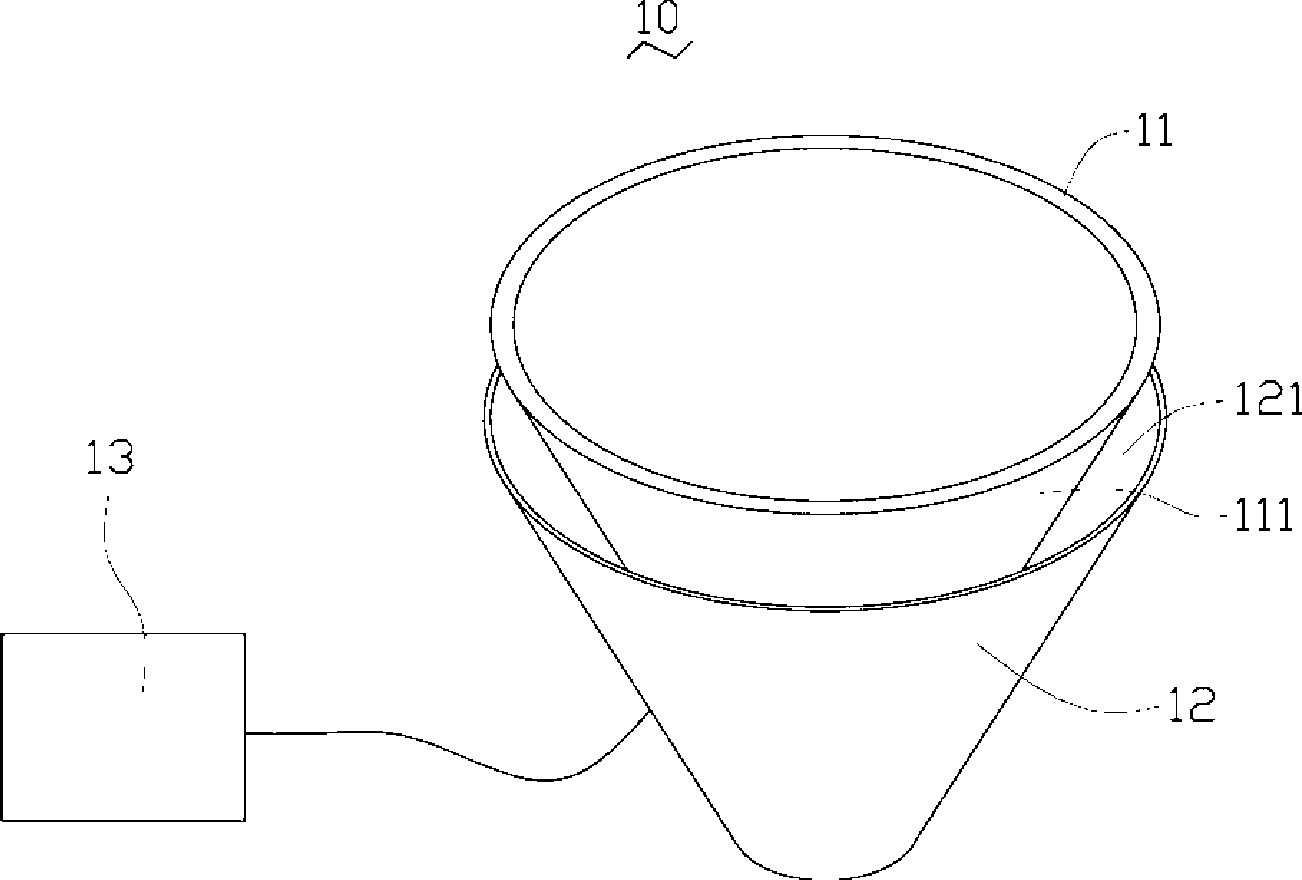
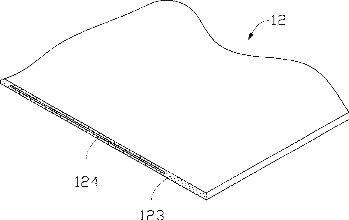
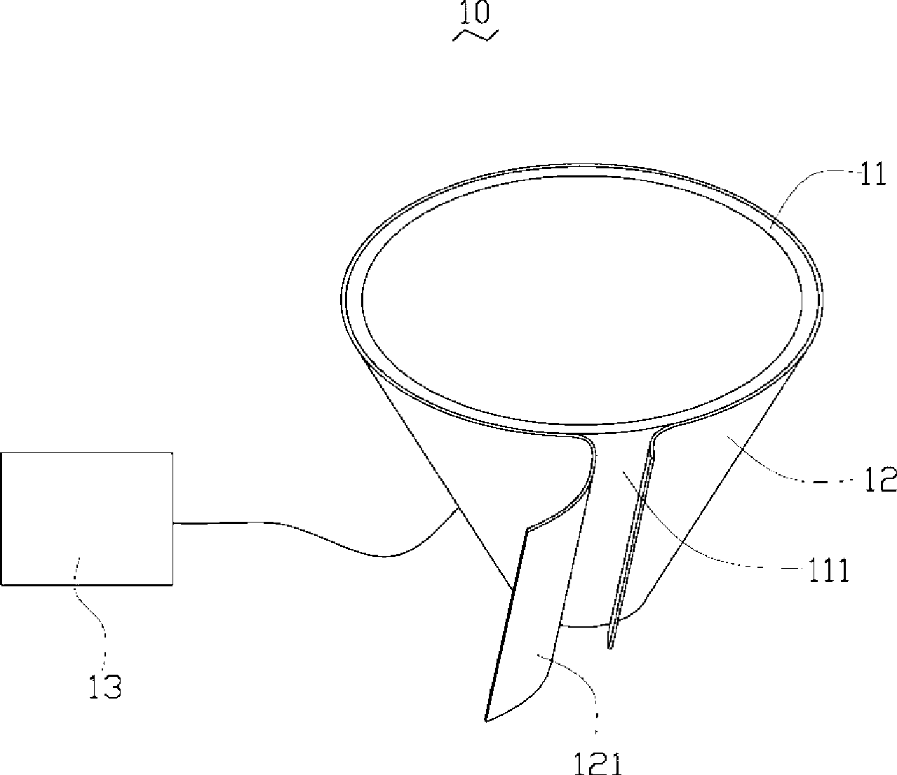
[0014] Please also refer to figure 1 , figure 2 and image 3 , which is the dehumidification container 10 provided by the first embodiment, which includes a container body 11 , a heating part 12 and a control part 13 .

[0015] The container body 11 is enclosed by a side wall 111 with good thermal conductivity, and is used for accommodating the material to be dehumidified (not shown). In this embodiment, the container body 11 is a conical hopper made of iron, and has a feeding port and a discharging port (not shown in the figure), which can be installed in the injection machine for feeding. Of course, the container body 11 can also be a cylinder, a sphere or other shapes. In addition, the container body 11 can also be made of metal materials with good thermal conductivity, such as iron alloys, cop...


PUM


Abstract

The invention provides a dehumidification vessel. The dehumidification vessel comprises a vessel body, a control part and at least one heating part. The vessel body is formed by enclosing sidewall with heat conduction and is used for receiving a material to be humidified. The heating part at least covers the sidewall of part of the vessel body and comprises a heat conduction layer and an electrothermal layer embedded in the heat conduction layer. The control part is in electric connection with the heating part and is used for adjustably controlling the temperature of the heating part and the time for opening and closing the heating part. The dehumidification vessel can be conveniently used for conditions needing dehumidification.

Description

technical field [0001] The invention relates to a dehumidification container, in particular to a dehumidification container applied to molding machines such as injection molding machines, blow molding machines and foam molding machines. Background technique [0002] Injection molding has many advantages over other molding methods such as blow molding and foam molding. First, the molding cycle is short, only a few minutes at most. Secondly, the mass of the molded product is wide, ranging from a few grams to tens of kilograms. Again, injection molding can be done in one shot when molding products with complex shapes and precise dimensions, with metal or non-metal inserts such as ceramics, polymers, etc. Therefore, the use of injection molding to produce high-precision three-dimensional parts, as well as optical products in portable electronic products such as cameras, notebook computers and mobile phones, has become more and more popular. See Fabrication of piezoelectriccer...

Claims


Application Information

Patent Timeline
Patent Type & Authority Applications(China)
IPC IPC(8): B29C45/72
Inventor 林后尧
Owner HONG FU JIN PRECISION IND (SHENZHEN) CO LTD
Why Eureka
Try Eureka