Hollow carcass for filling cast-in-situ concrete

A hollow carcass, cast-in-place concrete technology, which is applied to floors, building materials, building components, etc., can solve the problems of low production efficiency, high cost, inconvenient production, etc. Effect

Inactive Publication Date: 2009-06-10
湖南邱则有专利战略策划有限公司
View PDF3 Cites 1 Cited by
  • Summary
  • Abstract
  • Description
  • Claims
  • Application Information

AI Technical Summary

Problems solved by technology

But when this kind of hollow carcass is applied to the floor construction, the hollow carcass cannot be accurately arranged in the middle layer of the floor, which affects the construction quality of the floor
For this reason, the patent No. is ZL01215092.4, and the name is "building component" utility model patent. The disclosed building component is a polyhedron, which can be hollow or solid. In order to ensure that this building component is applied to the floor It is arranged in the middle layer of the floor, and the outer wall of the polyhedron is provided with protruding legs, so that when the floor is poured, the legs can ensure that the hollow multi-faceted main cavity is just at the middle layer of the floor. , so as to better solve the above problems, but the production of this kind of building components is inconvenient, the production efficiency is low, it is not convenient for assembly line production, and the corresponding cost is high

Method used


Image

  • Hollow carcass for filling cast-in-situ concrete
  • Hollow carcass for filling cast-in-situ concrete
  • Hollow carcass for filling cast-in-situ concrete

Examples


Embodiment Construction

[0071] The present invention will be further described below in conjunction with the accompanying drawings and embodiments.

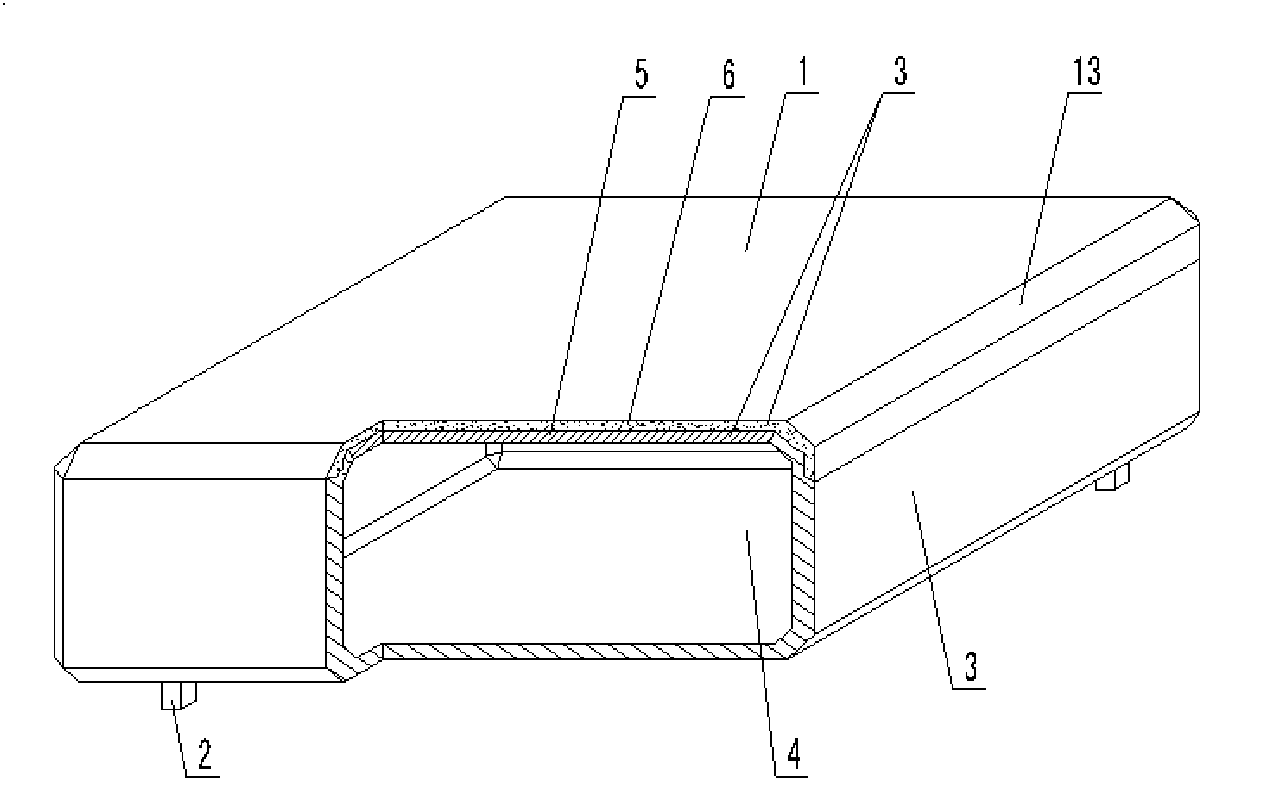
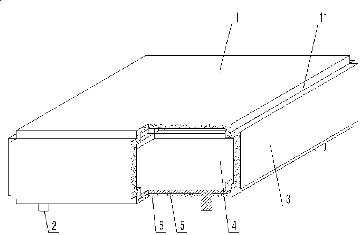
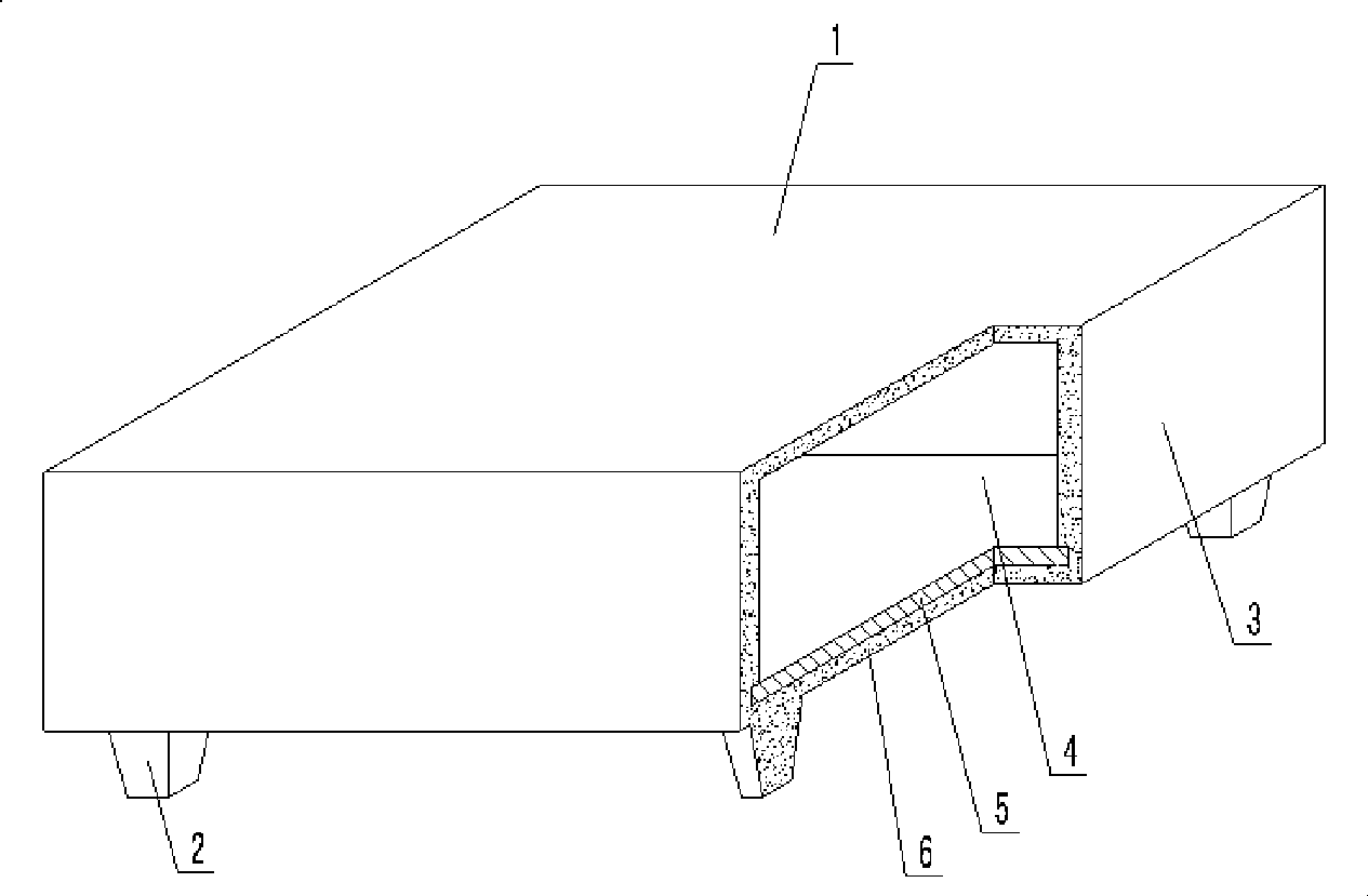
[0072] As shown in the accompanying drawings, the present invention includes a hollow carcass 1, a support foot 2, and an outer wall 3 enclosing the hollow carcass 1 with a cavity 4. It is characterized in that at least one outer wall 3 is an outer wall of a laminated layer. The prefabricated layer 5 in the laminated layer is arranged on the inner layer of the outer wall 3, the outer layer of the outer wall 3 is the freshly plastered layer 6, the upper outer wall 3 or the lower outer wall 3 is the outer wall of the laminated layer, and the cavity 4 is provided with a reinforcement 17 to strengthen Part 17 is a prefabricated hollow rod, and the two ports of the hollow rod communicate with the outside of the upper and lower outer walls 3 to form a connected hole 16. In each accompanying drawing, 1 is a hollow carcass, 2 is a support foot, 3 is an outer wa...


PUM


Abstract

The invention relates to a hollow matrix for filling cast-in-situ concrete, which comprises a hollow matrix (1) and an arm brace (2), wherein the outer wall (3) forms the hollow matrix (1) provided with a cavity (4) in an enclosed form. The hollow matrix for filling the cast-in-situ concrete is characterized in that at least one outer wall (3) is the outer wall of an overlapping layer; a precast layer (5) in the overlapping layer is arranged on an inner layer of the outer wall (3); an outer layer of the outer wall (3) is a cast-in-situ layer (6); an upper outer wall (3 ) or a lower outer wall (3) is the outer wall of the overlapping layer; a reinforcement (17) is arranged inside the cavity (4) and is a precast hollow member bar; two ports of the hollow member bar are communicated with exteriors of the upper outer wall (3) and the lower outer wall (3) to form a communicated hole (16); a bottom outer wall (3) is the outer wall of the overlapping layer; and the arm brace (2) is arranged on the bottom outer wall (3). The hollow matrix for filling the cast-in-situ concrete is suitable to be used by cast-in-situ reinforced concrete or prestressed reinforced concrete hollow slabs, floor, roof covers, wall bodies, foundation slabs and bridges and is particularly suitable to be used by hollow girderless floor.

Description

[0001] This application is a divisional application of an invention patent application with an application date of September 2, 2004, an application number of 200410155278.2, and a title of "a hollow matrix for filling cast-in-place concrete". (1) Technical field [0002] The invention relates to a hollow matrix for filling cast-in-place concrete. (2) Background technology [0003] At present, the cast-in-place concrete hollow floor is a widely used floor structure. The lightweight permanent tire molds filled in it include various hollow tubes and boxes, and the boxes are hollow or solid. For example, the patent No. ZL99249798.1, which the applicant applied for on November 29, 1999, is a utility model patent named "fiber-reinforced thin-walled member for reinforced concrete filling", which discloses a thin-walled formwork member, including an upper plate, The surrounding side walls, the lower bottom, and the upper plate, the surrounding side walls and the lower bottom form a...

Claims


Application Information

Patent Timeline
IPC IPC(8): E04C1/00E04C1/39E04C1/40E04B5/36E04B5/18
Inventor 邱则有
Owner 湖南邱则有专利战略策划有限公司
Why Eureka
Try Eureka