
Multi-wafer intersecting stacking encapsulation construction

A technology of chip packaging and stacking structure, applied in the direction of electrical components, electrical solid devices, circuits, etc., can solve problems such as troublesome, difficult, and complicated manufacturing processes

Active Publication Date: 2009-06-10
CHIPMOS TECH INC
View PDF8 Cites 0 Cited by
  • Summary
  • Abstract
  • Description
  • Claims
  • Application Information

AI Technical Summary

Problems solved by technology

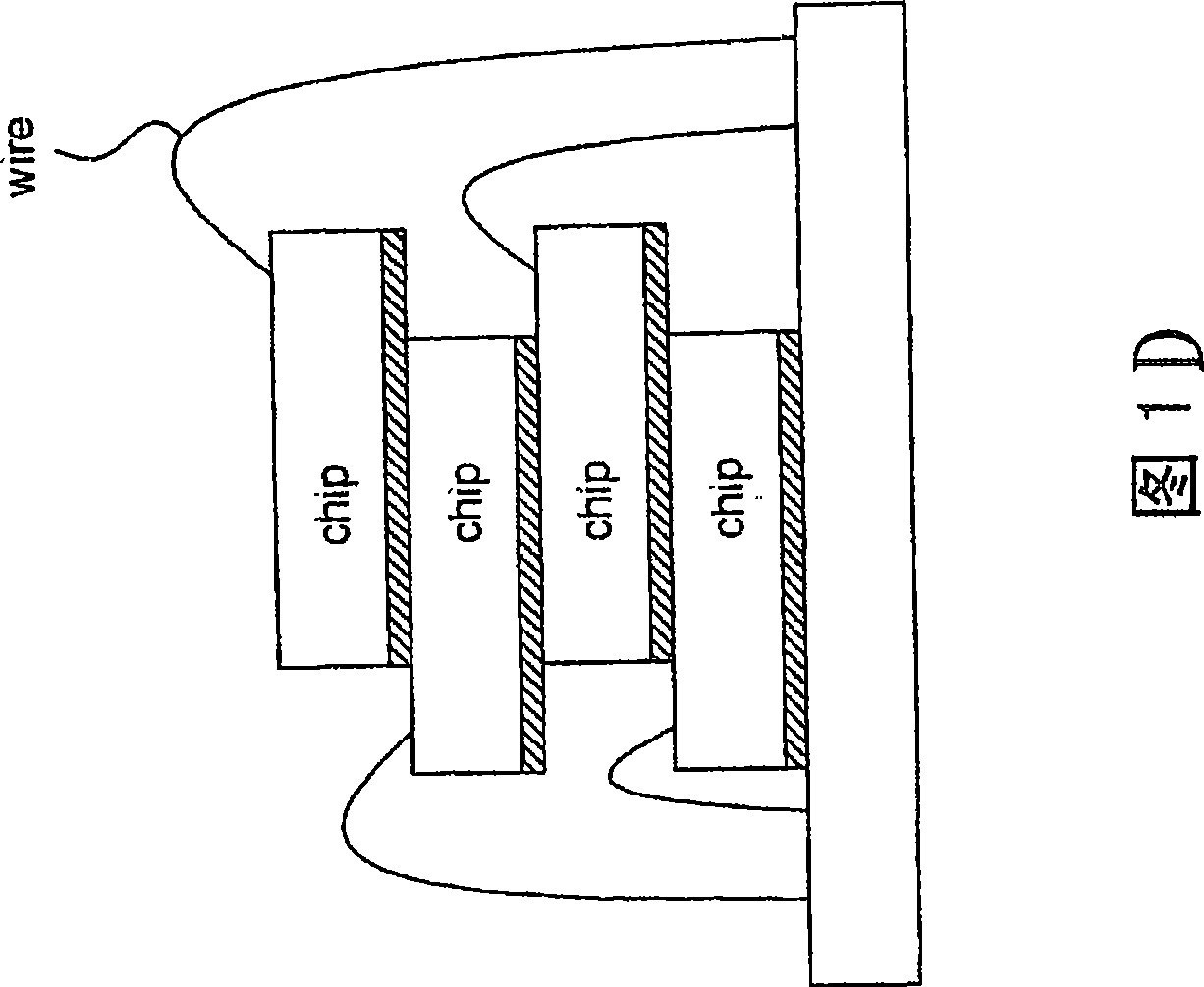
Figure 1D discloses an alternately stacked packaging structure. Obviously, it uses the height between chips to replace the spacers, so that the density of the package can be increased, but this packaging structure still has troubles in the process, that is, it must first After the connection of two chips is completed, the first metal wire connection can be carried out, and then the other two chips can be connected, and then the second metal wire connection can be carried out. Therefore, when the number of chips increases, the manufacturing process is relatively complicated. difficulty

Method used


Image

  • Multi-wafer intersecting stacking encapsulation construction
  • Multi-wafer intersecting stacking encapsulation construction
  • Multi-wafer intersecting stacking encapsulation construction

Examples


Embodiment Construction

[0032] The direction discussed in the present invention is to stack a plurality of chips with similar or different sizes into a three-dimensional packaging structure by using alternate staggered stacking of chips. In order to provide a thorough understanding of the present invention, detailed steps and components thereof will be set forth in the following description. Obviously, the practice of the invention is not limited to the specific details of the manner in which wafers are stacked, with which those skilled in the art are familiar. On the other hand, well-known wafer formation methods and detailed steps of back-end processes such as wafer thinning are not described in detail to avoid unnecessary limitations of the present invention. However, for the preferred embodiments of the present invention, it will be described in detail as follows, but in addition to these detailed descriptions, the present invention can also be widely implemented in other embodiments, and the sco...


PUM


Abstract

The invention provides a multi-wafer zigzag stack packaging structure, which comprises a lead frame, a multi-wafer zigzag stack structure and a plurality of metal conductors, wherein the lead frame comprises a plurality of first inner pins and second inner pins, which are in relatively staggered arrangement; the multi-wafer zigzag stack structure is fixedly connected with the lead frame, and consists of a plurality of first wafers and second wafers, which are in zigzag stack; a plurality of weld pads are arranged and exposed near one side of an active surface of each first wafer; a plurality of weld pads are also arranged and exposed near the other side of the active surface of each second wafer, relative to the exposed weld pads of the first wafers; and the metal conductors are used for electrically connecting the weld pads on the first wafers and the second wafers of the multi-wafer zigzag stack structure with the first and second inner pins.

Description

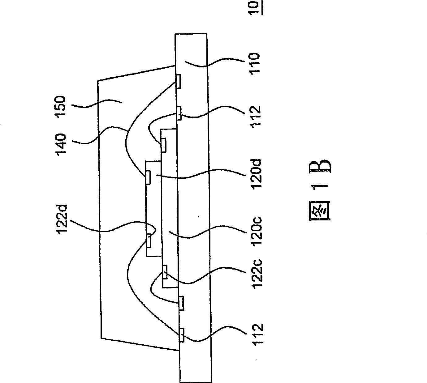
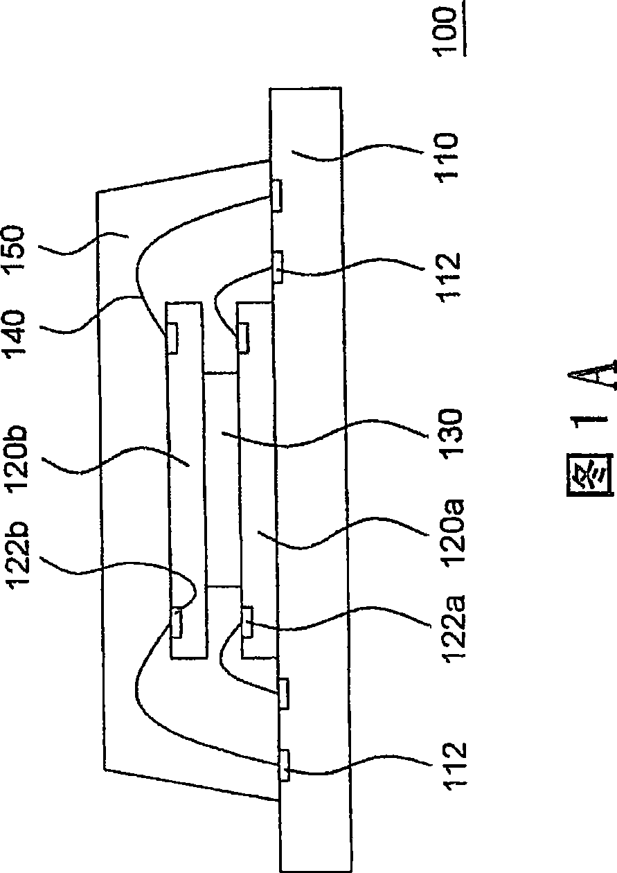
technical field [0001] The present invention relates to a multi-chip interleaving and stacking packaging structure, in particular to a multi-chip interleaving and interleaving stacking (zigzagstack) packaging structure. Background technique [0002] In recent years, three-dimensional (3D) packaging is being carried out in the back-end process of semiconductors, in order to use the least area to achieve a relatively large integrated semiconductor or memory capacity. In order to achieve this goal, a chip stacked method has been developed to achieve a three-dimensional (Three Dimension; 3D) package at this stage. [0003] In the known technology, the chip stacking method is to stack a plurality of chips on a substrate, and then use a wire bonding process to connect the plurality of chips to the substrate. FIG. 1A is a schematic cross-sectional view of a known stacked chip package structure with the same or similar chip size. As shown in FIG. 1A, a known stacked chip package s...

Claims


Application Information

Patent Timeline
IPC IPC(8): H01L25/00H01L25/065H01L23/488H01L23/495H01L23/31
CPCH01L2224/48247H01L2224/32225H01L2224/48145H01L2224/48227H01L2224/32245H01L2224/73265H01L2224/32145H01L2225/06562H01L24/73H01L2224/023H01L2924/181H01L2924/00012H01L2924/00H01L2924/0001
Inventor 陈煜仁
Owner CHIPMOS TECH INC
Learn More