
Pneumatic tire

A technology for pneumatic tires and tires, applied in tire parts, tire tread/tread pattern, transportation and packaging, etc., to eliminate poor rigidity and improve uneven wear resistance.

Inactive Publication Date: 2009-06-10
THE YOKOHAMA RUBBER CO LTD
View PDF2 Cites 3 Cited by
  • Summary
  • Abstract
  • Description
  • Claims
  • Application Information

AI Technical Summary

Problems solved by technology

However, in either proposal, there is a limit to uniform tread pattern rigidity over the entire circumference of the tire.

Method used


Image

  • Pneumatic tire
  • Pneumatic tire
  • Pneumatic tire

Examples


Embodiment

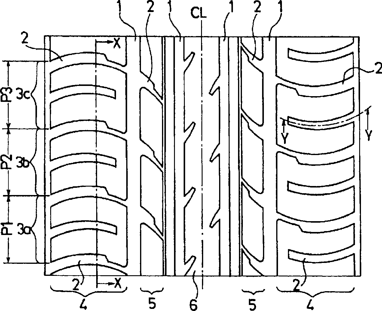
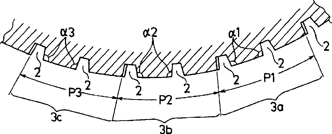
[0046] 20 comparative tires (comparative examples 1 and 2) and tires of the present invention (embodiments 1 to 3) were produced respectively, wherein: the tire size was set to 275 / 35R20 and the tread pattern was set to figure 1 Thus, the ratio of the groove area for each pitch and the groove wall angle α on the side of the obtuse angle formed by the groove wall of the lateral groove and the tangential direction of the tread surface were varied as shown in Table 1. In addition, in each tire, the pitch lengths P1, P2, and P3 of the three types of pitches were set to P1 (large pitch 3a) = 40mm, P2 (intermediate pitch 3b) = 35mm, and P3 (small pitch) = 30mm.

[0047] For the above five types of tires, uniformity (RFV: Radial Force Variation) was measured in accordance with JIS (Japanese Industrial Standards: Japanese Industrial Standards) D4233, and the number of tires with the reference value (108N) cleared The evaluation of the uniformity was performed, and the results are sho...


PUM


Abstract

To provide a pneumatic tire with an improved uniformity, in which pitch variation is adopted for suppressing pattern noise. The ratios of groove area in pitches (3a, 3b, 3c) with different pitch lengths are set to be smaller in pitches with longerr pitch lengths. Groove wall angles a on the obtuse angle side that is formed by the groove walls of lateral grooves (2) and the tangential direction of the tread surface are larger in the pitches with longer pitch lengths.

Description

technical field [0001] The present invention relates to a pneumatic tire, and more specifically, to a pneumatic tire capable of improving uniformity while suppressing disruption of the rigidity balance in the circumferential direction of a tire employing a pitch variation technique for suppressing tread pattern noise. Background technique [0002] In general, in pneumatic tires, in order to reduce various noises generated by the tread pattern of the tire, the following processing is performed: the block pattern is appropriately arranged in the tire circumferential direction on the tread surface with a plurality of pitches with different pitch lengths. Arranged in combination, the pitch noise is dispersed into a wider frequency, and the noise characteristics of the tire are improved. However, when the blocks are arranged at different pitches in the tire circumferential direction, a difference in rigidity occurs between the blocks having a larger pitch length and the blocks ha...

Claims


Application Information

Patent Timeline
Patent Type & Authority Applications(China)
IPC IPC(8): B60C11/03B60C11/01B60C11/04B60C11/13
CPCB60C11/13B60C11/0316B60C11/0318
Inventor 大木幸彦
Owner THE YOKOHAMA RUBBER CO LTD
Learn More