Direct drive type hydraulic variable pitch controlling mechanism for wind power generator

A wind turbine and control mechanism technology, applied in the control of wind turbines, wind turbines, wind power generation, etc., can solve the problems of complex hydraulic circuits, low reliability, and no redundant control, so as to achieve reliable control and simplified hydraulic pressure. circuit, the effect of reducing the probability of failure

Active Publication Date: 2009-08-05
哈尔滨工业大学高新技术开发总公司
View PDF0 Cites 12 Cited by
  • Summary
  • Abstract
  • Description
  • Claims
  • Application Information

AI Technical Summary

Problems solved by technology

[0005] The present invention aims at the defects of complex hydraulic circuit and low reliability of the hydraulic pitch control mechanism of the existing wind power generator, and the defects of no redundant control, and proposes a direct-drive hydraulic pitch change for the wind power generator control mechanism

Method used


Image

  • Direct drive type hydraulic variable pitch controlling mechanism for wind power generator
  • Direct drive type hydraulic variable pitch controlling mechanism for wind power generator
  • Direct drive type hydraulic variable pitch controlling mechanism for wind power generator

Examples


specific Embodiment approach 1

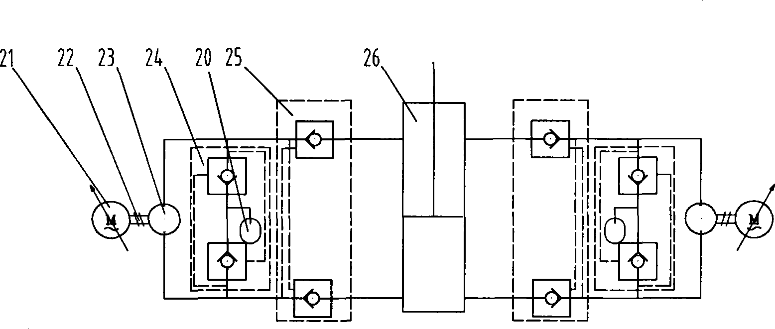
[0009] Specific implementation mode one: combine image 3 Describe this embodiment, the direct-drive hydraulic pitch control mechanism in this embodiment consists of a closed oil tank 20, an AC servo motor 21, a shaft coupling 22, a bidirectional quantitative pump 23, an oil replenishment valve 24, and a bidirectional hydraulic lock 25 It is composed of variable pitch hydraulic cylinder 26; the power output shaft of AC servo motor 21 is connected with the power input shaft of bidirectional quantitative pump 23 through coupling 22, and the AC servo motor 21 clockwise or counterclockwise after receiving the voltage signal of the variable pitch controller. The clockwise rotation drives the two-way quantitative pump 23 to rotate, outputs pressure oil to the variable pitch hydraulic cylinder 26, and pushes the piston rod of the hydraulic cylinder to move, thereby adjusting the pitch angle of the blades to meet the optimal working condition of the generator; When the feedback signal...

specific Embodiment approach 2

[0010] Specific implementation mode two: combination Figure 4 Describe this embodiment, the difference between this embodiment and the specific embodiment is that the normally open two-position two-way solenoid valve 28, the normally closed two-position two-way solenoid valve 29 and the hydraulic accumulator 31 are added; the pitch hydraulic cylinder 26 The rod chamber of the hydraulic cylinder 26 communicates with the closed oil tank 20 through the normally open two-position two-way solenoid valve 28; the rodless chamber of the variable pitch hydraulic cylinder 26 communicates with the hydraulic accumulator 31 through the normally closed two-position two-way solenoid valve 29; The normally open two-position two-way solenoid valve 28 and the normally closed two-position two-way solenoid valve 29 are energized during pitch adjustment and remain closed. At this time, the other parts of the direct-drive hydraulic pitch control mechanism work in the same way as the specific Imple...

specific Embodiment approach 3

[0011] Specific implementation mode three: combination Figure 4 Describe this embodiment, the difference between this embodiment and the specific embodiment 1 or 2 is that a manual shut-off valve 27 is added, and the three oil ports of the manual shut-off valve 27 are connected with the oil inlet and outlet ports of the closed oil tank 20 and the pitch hydraulic pressure respectively. The rod chamber of cylinder 26 is connected with the oil inlet and outlet of the rodless chamber. The manual stop valve 27 is usually closed, and the two cavities of the pitch hydraulic cylinder 26 and the closed oil tank 20 are locked. When it is necessary to maintain the direct-drive hydraulic pitch mechanism, the manual cut-off valve 27 can be opened to connect the two cavities of the pitch hydraulic cylinder 26 with the closed oil tank 20, and the pressure in the pitch hydraulic cylinder 26 can be removed. , the pitch hydraulic cylinder 26 can be maintained. Other compositions and connecti...


PUM


Abstract

The invention relates to a direct driving type hydraulic propeller-pitch variation control mechanism of a wind powered generator, which belongs to the technique field of wind power generating equipment. The invention provides the direct driving type hydraulic propeller-pitch variation control mechanism which comprises a closed type oil tank, an alternating current servo motor, a two-way constant rate pump, an oil supplementing valve, a hydraulic lock and a propeller-pitch variation hydraulic cylinder aiming at the problem of the complex hydraulic loop and the low reliability and the defect of no redundant control of a hydraulic propeller-pitch variation control mechanism of a prior wind powered generator. In addition, a power output shaft of the alternating current servo motor is connected with a power input shaft of the two-way constant rate pump which is connected with the propeller-pitch variation hydraulic cylinder through the hydraulic lock, the closed type loop is formed by two oil ways positioned between the two-way constant rate pump and the propeller-pitch variation hydraulic cylinder, two oil inlet and outlet openings of the oil supplementing valve are respectively connected with the two oil ways positioned between the two-way constant rate pump and the propeller-pitch variation hydraulic cylinder, and a third oil inlet and outlet opening of the oil supplementing valve is connected with an oil inlet and outlet opening of the closed type oil tank. The invention has the advantages of simple structure, reliable control, light weight, small floor area, and the like.

Description

technical field [0001] The invention relates to the technical field of wind power generation equipment, in particular to a hydraulic pitch control mechanism of a wind power generator. Background technique [0002] There are two types of large wind turbines, fixed pitch and variable pitch. The windward angle of the fixed-pitch fan is fixed. When the wind force is greater than a certain value, the speed will be too high and the unit cannot work normally. Adjust the pitch angle at any time to control the absorbed mechanical energy, on the one hand to ensure the maximum energy (corresponding to the rated power), and to reduce the impact of wind on the wind turbine. In the process of grid connection, pitch control can also realize fast grid connection without impact. The variable pitch control system cooperates with variable speed and constant frequency technology, which ultimately improves the power generation efficiency and power quality of the entire wind power generation sy...

Claims


Application Information

Patent Timeline
Patent Type & Authority Applications(China)
IPC IPC(8): F03D7/02F15B15/18F15B20/00
CPCY02E10/723Y02E10/72
Inventor 苏文海姜继海刘庆和连欢
Owner 哈尔滨工业大学高新技术开发总公司
Why Eureka
Try Eureka