Wire winding system, tension device, and wire winding method
A technology of winding device and tensioning device, which is applied in the direction of coil manufacturing, transportation and packaging, electrical components, etc., can solve the problem of keeping the tension of difficult wires constant, and achieve the effect of suppressing the change of tension
- Summary
- Abstract
- Description
- Claims
- Application Information
AI Technical Summary
Problems solved by technology
Method used
Image

Examples
no. 1 Embodiment approach
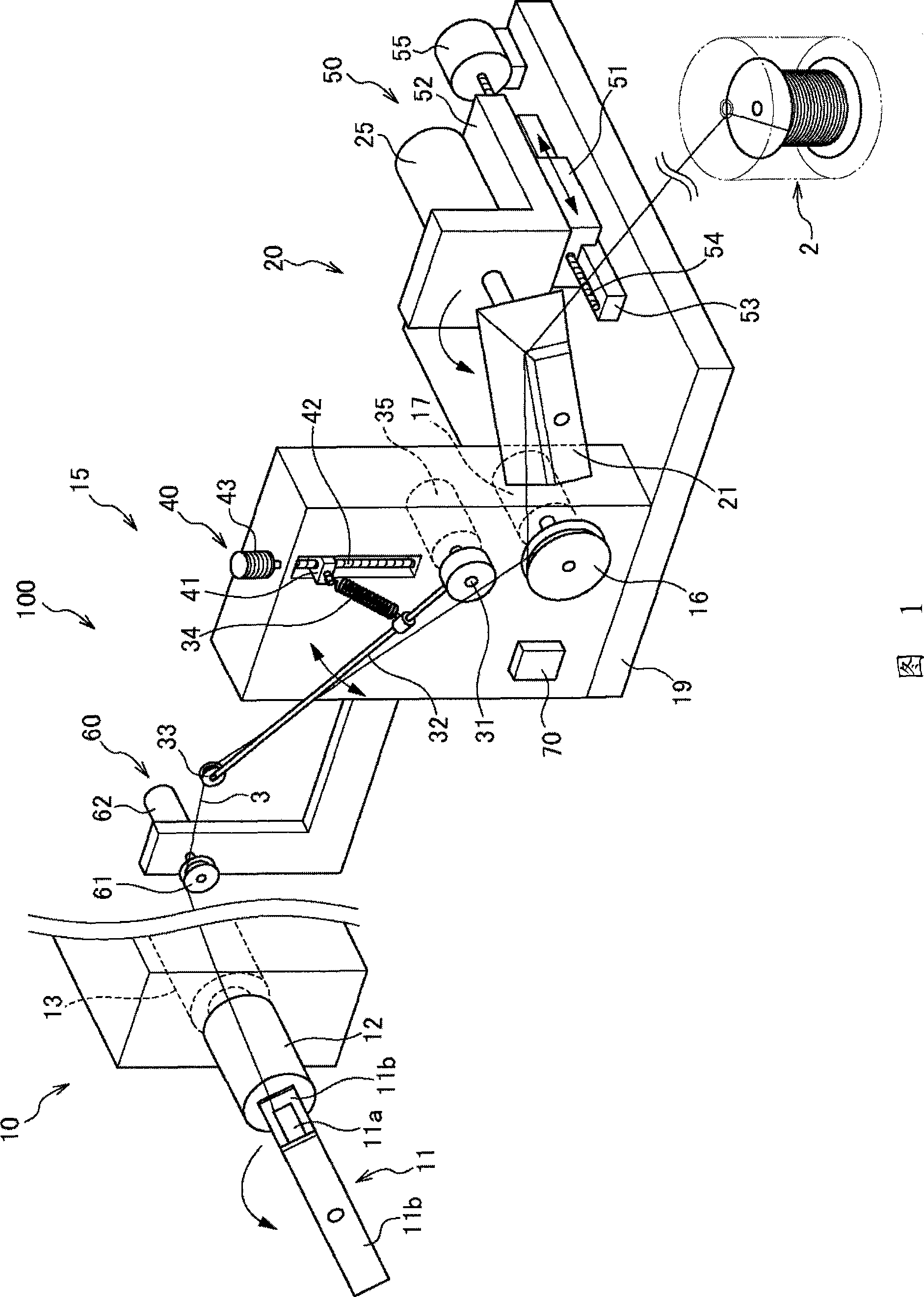
[0013] Referring to FIG. 1 , a wire winding device 100 according to a first embodiment of the present invention will be described. FIG. 1 is a perspective view showing a winding device 100 .
[0014] The winding device 100 is a device for manufacturing a coil by winding the wire 3 supplied from the wire supply source 2 around a winding core (coil reel) 11 that rotates around the axis center line.
[0015] The winding device 100 includes: a winding machine 10 that drives the winding core 11 to rotate around the shaft center line; the wire 3 supplied from the wire supply source 2 is supplied to the wire payout machine 20 on the winding core 11; A tensioning device 15 for the tension of the wire 3 of the winding machine 10; a controller 70 for controlling the winding action.
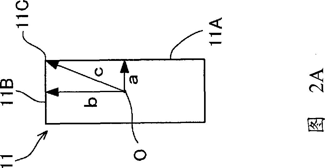
[0016] The winding core 11 is composed of a trunk portion 11a around which the wire 3 is wound, and flange portions 11b provided on both end surfaces of the trunk portion 11a to regulate the winding width ...
no. 2 Embodiment approach
[0065] Referring to FIG. 3 , a winding device 200 according to a second embodiment of the present invention will be described. FIG. 3 is a perspective view showing the winding device 200 .
[0066] The same reference numerals are assigned to the same configurations of the wire winding device 200 of the present embodiment as those of the wire winding device 100 of the first embodiment described above, and description thereof will be omitted. Hereinafter, it demonstrates centering on the difference from the winding device 100.
[0067] The difference between the bobbin winding device 200 and the bobbin winding device 100 of the above-mentioned first embodiment is that the partial structure of the tension device 15 is different.
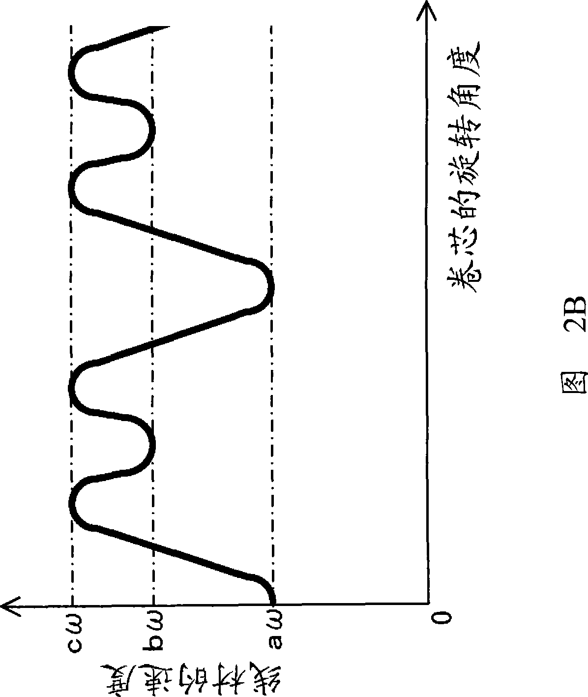
[0068] In the tensioning device 15 of the winding device 100 of the above-mentioned first embodiment, by controlling the rotation speed of the variable wire speed motor 17, the linear speed of the wire 3 fed out from the pulley 16 is changed, and the s...
PUM
 Abstract
Description
Claims
Application Information
 - R&D
- Intellectual Property
- Life Sciences
- Materials
- Tech Scout
- Unparalleled Data Quality
- Higher Quality Content
- 60% Fewer Hallucinations
Browse by: Latest US Patents, China's latest patents, Technical Efficacy Thesaurus, Application Domain, Technology Topic, Popular Technical Reports.
© 2025 PatSnap. All rights reserved.Legal|Privacy policy|Modern Slavery Act Transparency Statement|Sitemap|About US| Contact US: help@patsnap.com