
Rolling/drawing type laminated opening wire coating machine

A wire wrapping machine, rolling and drawing technology, applied in coating, arc welding equipment, metal material coating process, etc., can solve problems such as unsatisfactory, poor powder coating ability, uneven powder coating, etc. The filling rate is adjustable and the powder feeding uniformity is good.

Active Publication Date: 2010-12-08
刘少光
View PDF0 Cites 0 Cited by
  • Summary
  • Abstract
  • Description
  • Claims
  • Application Information

AI Technical Summary

Problems solved by technology

The existing powder core wire wrapping machine has poor powder wrapping ability (low filling rate), uneven and compact powder wrapping, which not only causes empty powder and powder leakage, but also often causes bursting problems during spraying. As a result, the The alloy composition of the sprayed layer does not meet the requirements; the main reasons for the above problems are: the belt unwinding machine is too fast and there is belt silt phenomenon, the structure of each group of rolling wheels is complicated, it is difficult to adjust the positioning, and the surface of the wheels is severely worn, which causes the gap to be too large and the steel belt Improper and unsatisfactory forming and closing. The mismatch between the powder feeding speed and the rolling wheel speed causes uneven powder feeding. The mismatch between the wrapping machine and the wire drawing machine speed results in broken wires. The type and thickness of the strip and core powder materials, It is difficult to manufacture various types of powder core wire due to high requirements on width and particle size

Method used


Image

  • Rolling/drawing type laminated opening wire coating machine
  • Rolling/drawing type laminated opening wire coating machine
  • Rolling/drawing type laminated opening wire coating machine

Examples


Embodiment Construction

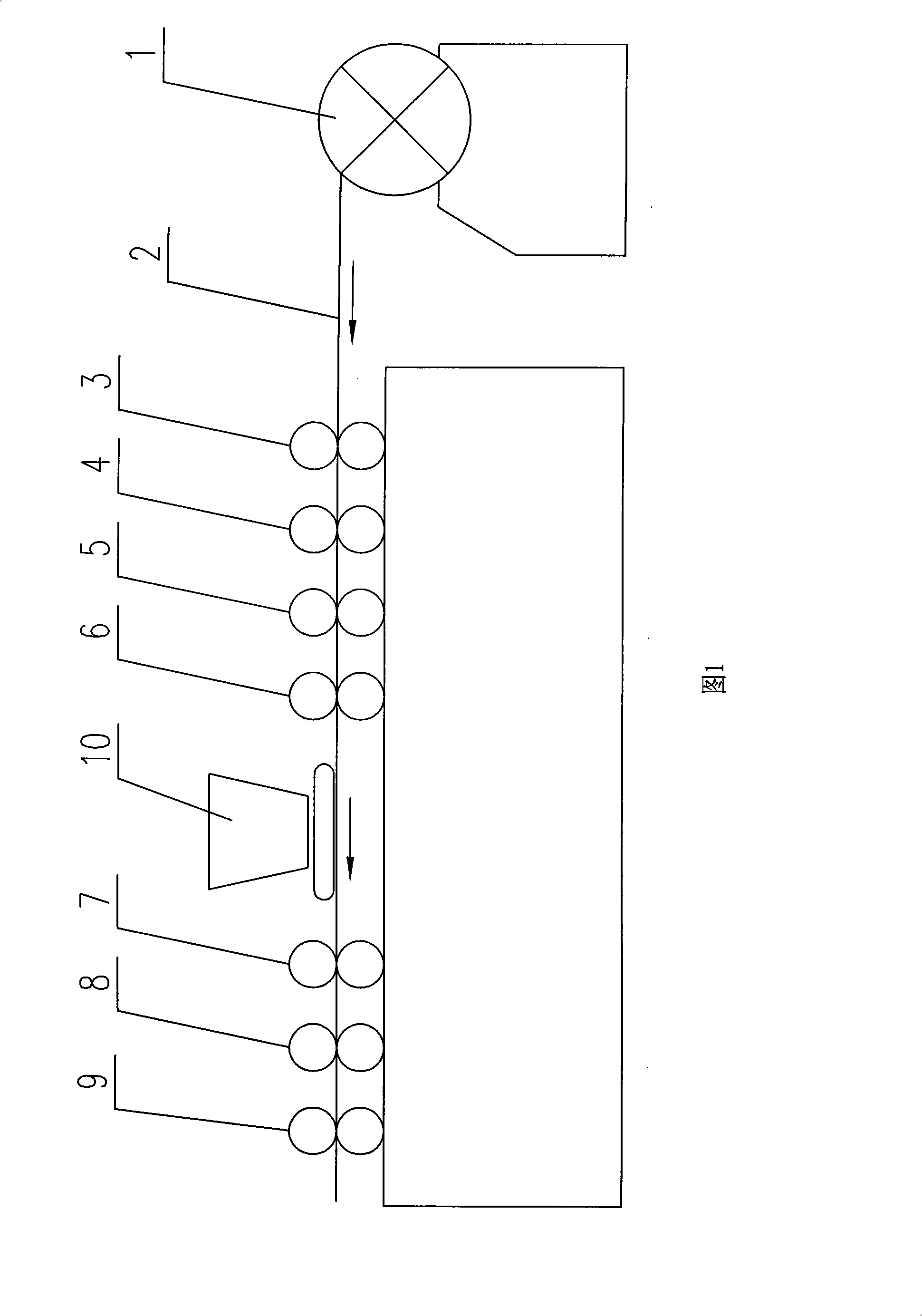
[0015] Such as figure 1 As shown, the present embodiment comprises a damping type unwinding mechanism 1, a rolling device, a powder feeder 10, and a closing device, wherein:

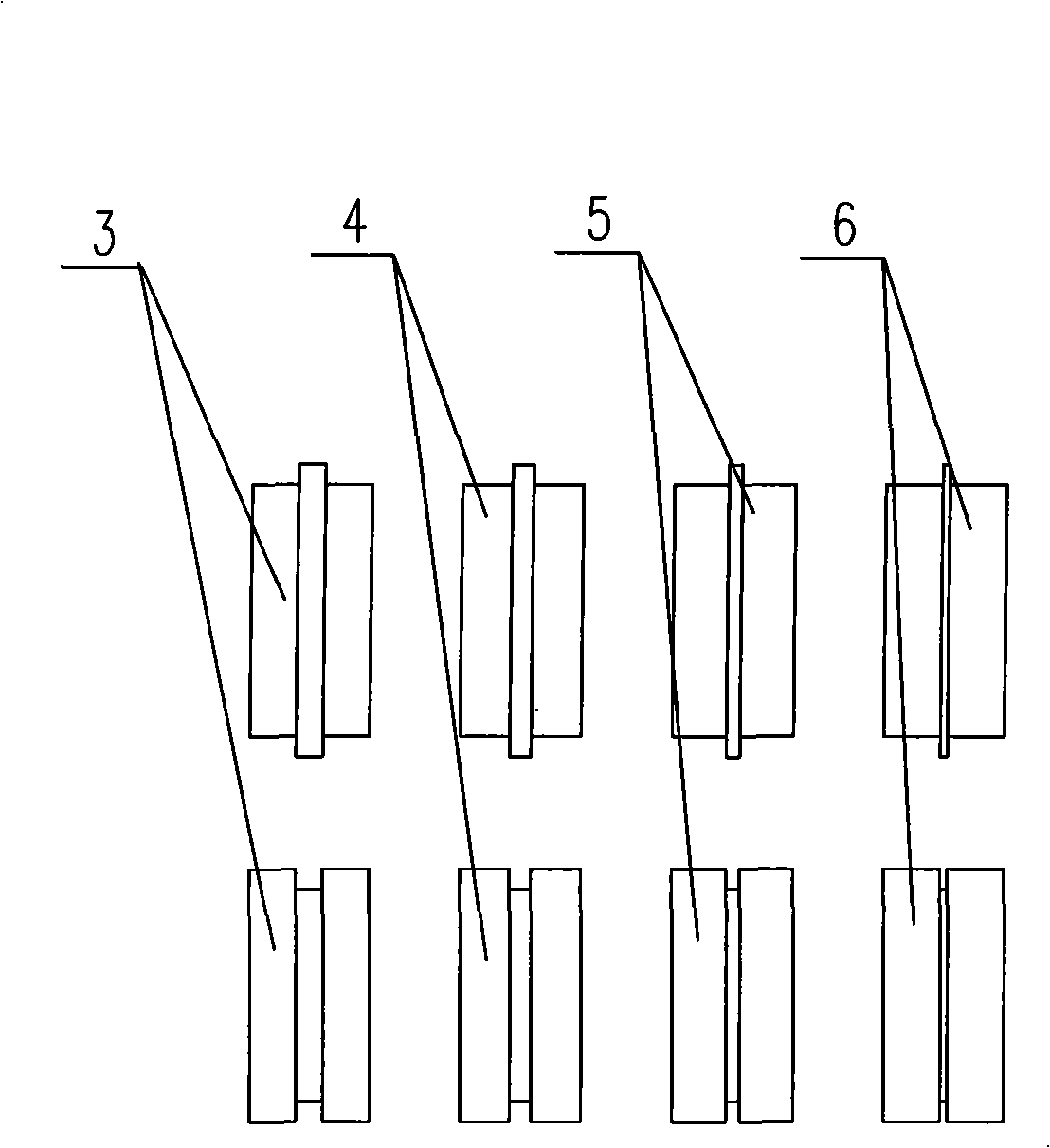
[0016] Such as figure 2 As shown, the rolling device is composed of positioning wheel 3, pre-rolling wheel 4, forming rolling wheel 5 and shaping rolling wheel 6, positioning wheel 3, pre-rolling wheel 4, forming rolling wheel 5 and shaping rolling wheel 6. The upper cam and the lower concave wheel are engaged respectively, and the width of the engagement gradually decreases from the positioning wheel, the pre-rolling wheel, the forming rolling wheel and the shaping rolling wheel in turn;

[0017] Such as Figure 4 As shown, the powder feeder 10 is located between the rolling device and the closing device, and it is composed of a powder feed funnel 15 and a conveyor belt 14. The length of the powder outlet of the powder feed funnel is slightly smaller than the width of the conveyor belt and evenly con...


PUM


Abstract

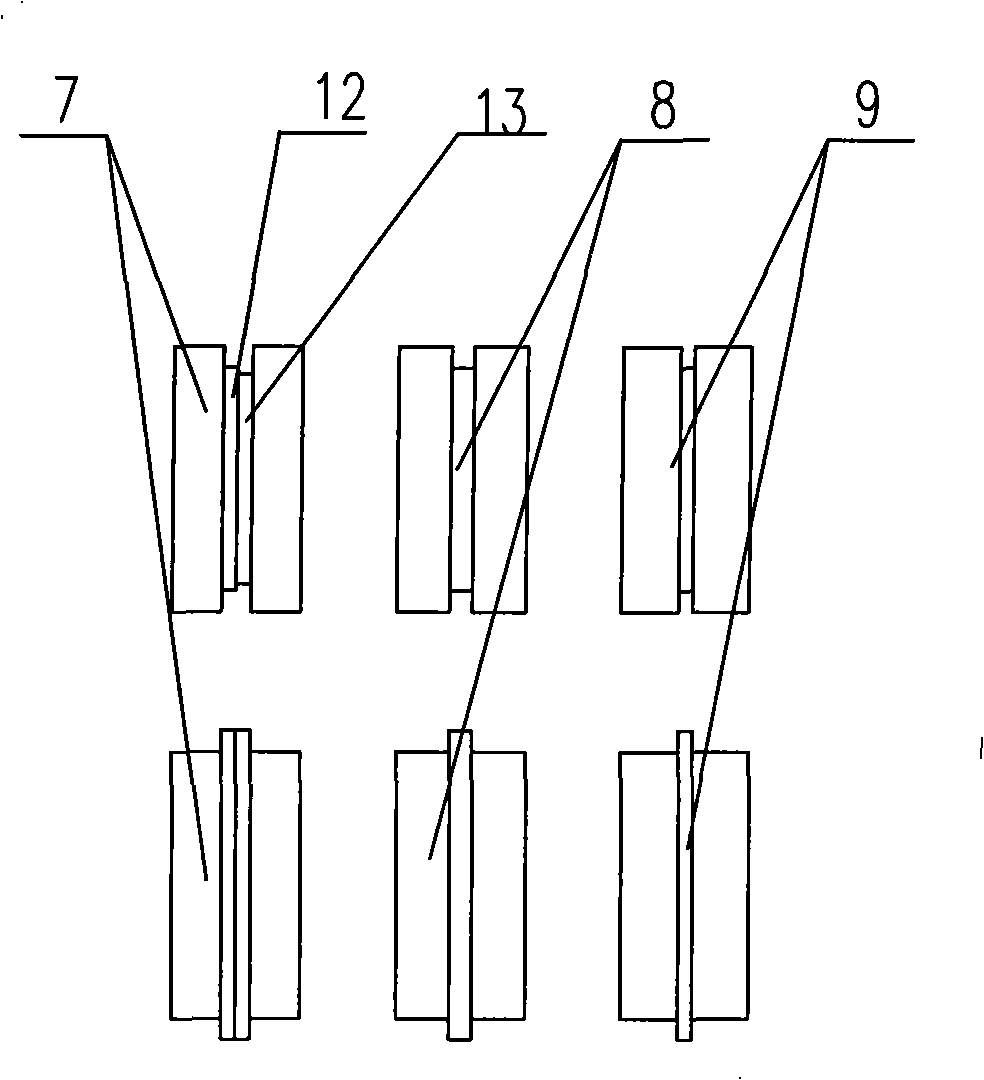
The invention relates to a wire wrapping machine of powder cored wires used for arc spraying and surfacing, in particular to a rolling / pulling-typed superposed wire wrapping machine; the wire wrapping machine comprises a damping-typed belt-arranging mechanism, a rolling device, a powder feeding device and a folding device; wherein, the rolling device consists of a locating wheel, a pre-rolling wheel, a forming rolling wheel and a shaping rolling wheel; the powder feeding device is arranged between the rolling device and the folding device and consists of a powder feeding funnel and a conveyerbelt; the folding device consists of a superposed rolling wheel, a sealed rolling wheel and a compacting rolling wheel; in the upper concave wheel of the superposed rolling wheel, the concave trough of the upper concave trough consists of two concave troughs of different depths. The invention aims at designing the rolling / pulling-typed superposed wire wrapping machine which can convey the powder uniformly, wrap the powder compactly and lead the steel belt to be formed correctly. Compared with the prior art, the wire wrapping machine has the advantages of uniform belt-arranging speed, high filling rate, high compactness of the powder core, capability of preventing the powder of the powder cored wires from leaking or being affected by moisture after forming a disc, and the like.

Description

technical field [0001] The invention relates to a wire wrapping machine for manufacturing powder core wire materials for arc spraying and surfacing welding, in particular to a rolling and drawing type lapping wire wrapping machine. Background technique [0002] Arc spraying technology is popular because of its easy operation, low cost, and high efficiency, but usually only materials with high plasticity, good toughness, low hardness, and low work hardening ability can be made into wires for arc spraying, which greatly restricts This limits the selection of materials and also limits the improvement of coating protection performance. The improved method is to use powder core wire structure, choose flexible metal strip as the skin material, and use high hardness, high oxidation resistance and corrosion resistance intermetallic compound, ceramic and cermet powder as the core powder material. [0003] Due to the particularity of the structure, the powder core wire needs to be pr...

Claims


Application Information

Patent Timeline
Patent Type & Authority Patents(China)
IPC IPC(8): C23C4/00B23K9/04C23C4/131
Inventor 刘少光陈久林陈成武江凤娟姚继蓬
Owner 刘少光
Learn More