Power closing latch device

A closed position and power technology, applied in electric vehicle locks, non-mechanical transmission-operated locks, building locks, etc., can solve problems such as difficult running time

Inactive Publication Date: 2009-06-17
VOLVO CAR CORP
View PDF0 Cites 17 Cited by
  • Summary
  • Abstract
  • Description
  • Claims
  • Application Information

AI Technical Summary

Problems solved by technology

Additional switches also result in more expensive electronics and wiring having to be installed
Thus, the more electronics used, the more difficult it is to maintain long operating times throughout the life of the vehicle

Method used


Image

  • Power closing latch device
  • Power closing latch device
  • Power closing latch device

Examples


Embodiment Construction

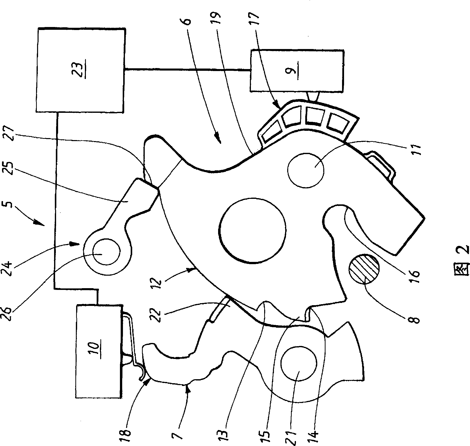
[0036] In the description below, various directions are given, such as front, rear, side, up, down. These directions are given with reference to a vehicle driving forward and the orientation of the particular embodiment shown in the drawings. The power closure latch arrangement according to the invention can be positioned in different ways, one possible positioning is shown in FIG. 2 . According to the invention, the striker can be fixed to the vehicle or to the pivot part of the vehicle and vice versa to the rest of the powered closure.

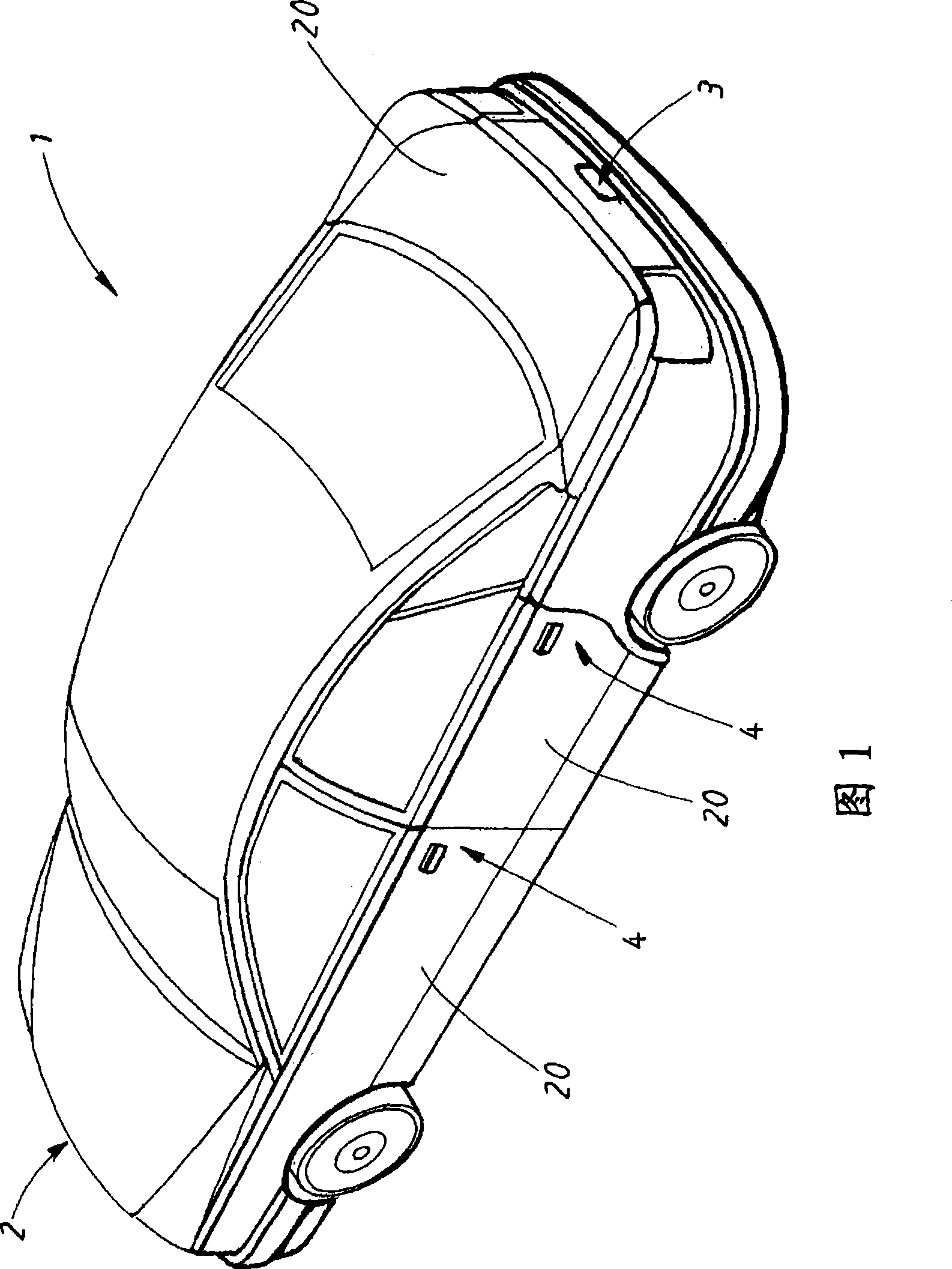
[0037] FIG. 1 shows a schematic perspective view of a vehicle 1 with a forward orientation 2 , a rear orientation 3 and a side orientation 4 . Vehicle doors, hoods, boot doors, luggage compartment doors or other doors may be automatically closed in the form of a power closing latch arrangement 5 according to an embodiment of the present invention.

[0038] Figure 2 shows a view of the power closure latch 5 in the open position. The illust...


PUM


Abstract

A power closing latch device for a door or lid in a vehicle, which device comprises a claw, a pawl and a striker. The pawl meshes with a safety recess and a lock recess of the claw in a safety position and a locked position. The striker is provided in a groove and rotates together with the claw, at closing of the door or lid. A spring is provided acting on the claw, which spring keeps the claw inthe safety position, when the door or lid is partially closed. An electric motor rotates the claw between the safety position and the closed position. An additional spring acting on the claw, which additional spring exert a counterforce on the claw to prevent the claw to stop in an undefined position, between the safety position and the closed position during a power closing process. A method forpower closing of a door or lid of a vehicle is also provided.

Description

technical field [0001] The present invention relates generally to a door or compartment door power closing latch arrangement for a vehicle, the power closing latch comprising a claw rotatable about a first pivot between an open position, a secure position and a locked position, the The claw has a safety notch and a locking notch; a claw (pawl), which is rotatable around a second pivot, engages the safety notch in the safety position and engages the locking notch in the locking position; position and the locked position are located in the groove of the claw, and the striker is arranged to advance into the claw in a linear motion from the open position to the safety position and to the locked position during closing of the door or compartment door; the spring acts the claw, the spring is arranged to hold the claw in the safe position when the door or hatch is partially closed; and the power closing unit is arranged to rotate the claw between the safe position and the closed posi...

Claims


Application Information

Patent Timeline
Patent Type & Authority Applications(China)
IPC IPC(8): E05B65/12E05B47/06
CPCE05B17/002E05B81/20E05B2047/0069E05B17/0037E05B77/34E05B81/66E05B81/68Y10T292/08
Inventor 克里斯特·多米尼克
Owner VOLVO CAR CORP
Why Eureka
Try Eureka