Self-adapting flexible vane rotor

A blade rotor, self-adaptive technology, applied in climate sustainability, engines, wind turbines at right angles to the wind direction, etc., can solve the problems of high R&D and production costs, complex control processes, unfavorable promotion and application, etc., and achieve easy maintenance. , High energy conversion efficiency, low cost effect

Inactive Publication Date: 2009-06-17
OCEAN UNIV OF CHINA +1
View PDF1 Cites 20 Cited by
  • Summary
  • Abstract
  • Description
  • Claims
  • Application Information

AI Technical Summary

Problems solved by technology

The PLC control circuit of this kind of device itself consumes a part of electric energy, and the lift force on the hydrofoil is determined by multiple parameters. The control process is more complicated, and the research and development and production costs are too high, which is not conducive to popularization and application.

Method used


Image

  • Self-adapting flexible vane rotor
  • Self-adapting flexible vane rotor
  • Self-adapting flexible vane rotor

Examples


Embodiment 1

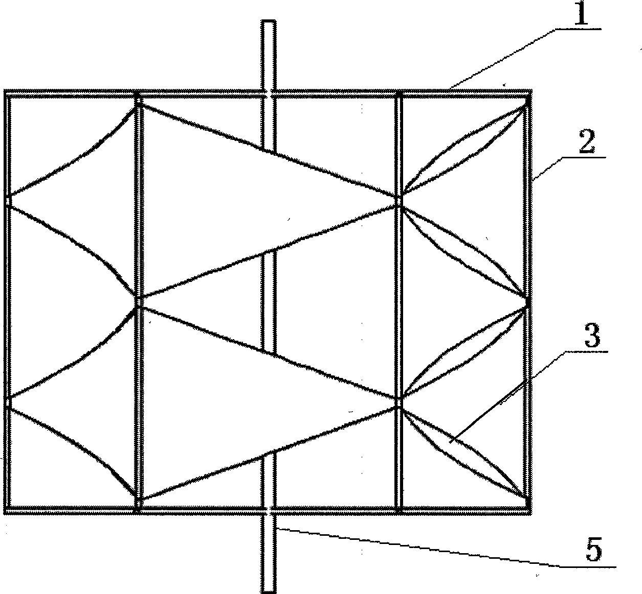
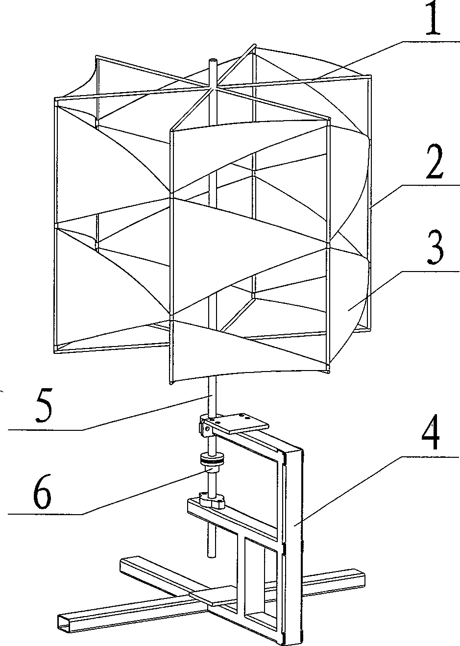
[0018] Such as figure 1 , 2 As shown, the application of the present invention in wind power generation, when the present invention is applied to wind power generation, it is called a flexible blade windmill, and the installation of the flexible blade rotor adopts a vertical axis installation method. It includes a central rotating shaft 5 , flexible blades 3 , a support layer, a fixed rod 2 , a fixed bracket 4 and an output drive wheel 6 . Two supporting layers perpendicular to the central rotating shaft 5 are arranged on the central rotating shaft 5, and the supporting layer adopts supporting rods 1 perpendicular to the central rotating shaft 5 and centered on the central rotating shaft 5 with the same interval angle and radially equal in length. The fixed rods 2 are arranged at intervals on the same circumference centered on the central rotating shaft 5 between the two support layers, the flexible blades 3 are arranged between the adjacent fixed rods 2, and the output drive...

Embodiment 2

[0021] The difference from Embodiment 1 is that: the central rotating shaft 5 is provided with three upper and lower support layers perpendicular to the central rotating shaft 5 . The supporting layer adopts support rods 1 perpendicular to the central rotating shaft 5 and centering on the central rotating shaft 5 to be radially equal in length at the same interval angle, and is arranged at intervals on the same circle centered on the central rotating shaft 5 between two adjacent supporting layers The fixed rods 2, the flexible blades 3 are arranged between the adjacent fixed rods 2. The flexible blades 3 are arranged in an equilateral triangle and an isosceles trapezoid at intervals, and the direction in which the flexible blades 3 of the equilateral triangle and isosceles trapezoid are arranged is consistent with the central rotating shaft 5 .

Embodiment 3

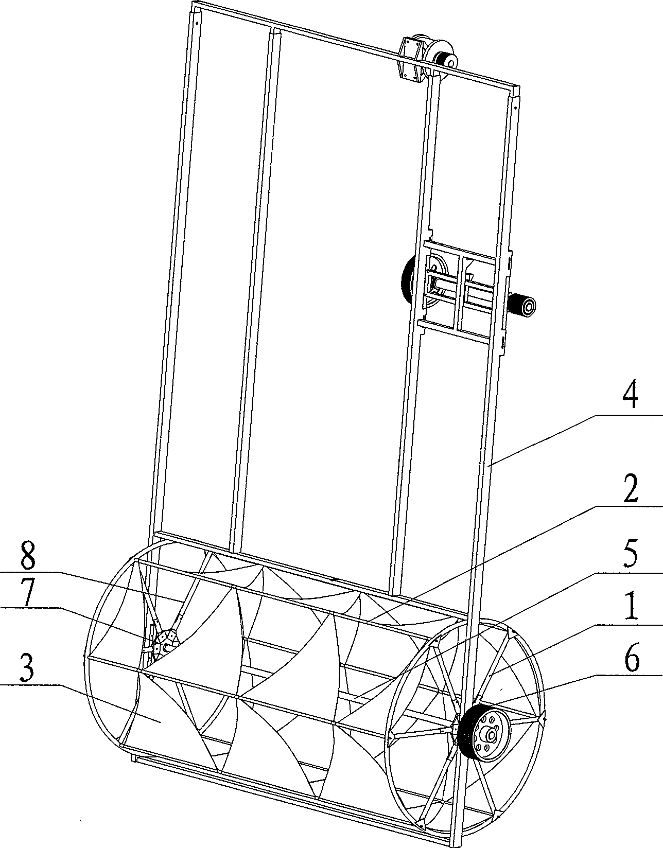
[0023] Such as image 3 As shown, the application of the present invention in hydropower generation, when the present invention is applied to hydropower generation, it is called a flexible blade water turbine, and the flexible blade rotor adopts a horizontal axis installation method. It includes a central rotating shaft 5, a flange 7, a fixed rod 2, a flexible blade 3, a fixed bracket 4 and an output drive wheel 6. On the central rotating shaft 5, two supporting layers perpendicular to the central rotating shaft 5 are arranged on the left and right. Between the two supporting layers The fixed rods 2 are arranged at intervals on the same circumference centered on the central rotating shaft 3, and the flexible blades 3 are arranged between adjacent fixed rods 2, and have a certain degree of slack. The plane formed by 2 can produce concave-convex deformation, the output driving wheel 6 is connected with the central rotating shaft 3 through a key, and the whole device is fixed on ...


PUM


Abstract

The invention relates to a fluidic impact generator, in particular to a generator rotor. The self-adapting flexible vane rotor of the invention comprises a central rotating shaft, a rotating wheel and fixed supports, wherein, the central rotating shaft and the rotating wheel are arranged in interference fit and are fixed and limited by the fixed supports, two supporting layers which are perpendicular to the central rotating shaft are at least arranged on the central rotating shaft, fixed links are arranged at intervals on the same circumference which is arranged between the two adjacent supporting layers and adopts the central rotating shaft as the center, and the adjacent fixed links are connected by flexible vanes; and corresponding to a plane formed by the two fixed links connected with the flexible vanes, the flexible vanes can be convexly and concavely deformed. The rotor can generate the torque larger than that of the rigid vanes and has higher energy utilization coefficient, thus the rotor has high energy conversion efficiency and can be widely utilized in the fluidic fields of wind energy, tidal power, etc.

Description

technical field [0001] The invention relates to a fluid impact generator, in particular to a generator rotor. Background technique [0002] With the emergence of the energy crisis and the deteriorating environment, green and clean energy has attracted more and more attention from all over the world. Wind energy and tidal current energy have become the focus of the development and utilization of renewable energy. The most effective form of water energy. Although wind power and tidal current power generation are truly clean energy sources, they are limited by factors such as large one-time investment, high technical requirements, and low energy acquisition efficiency. As auxiliary energy sources for electric energy, it is difficult to promote them. It will be of great significance to invent a low-cost, high-efficiency energy-changing rotor. [0003] At present, the main device for extracting wind energy is a rigid blade rotor, which has a low energy capture coefficient and a...

Claims


Application Information

Patent Timeline
Patent Type & Authority Applications(China)
IPC IPC(8): F03D3/06F03B3/12
CPCY02E10/223Y02E10/74Y02E10/20
Inventor 王树杰王天琪李冬鹿兰帅赵龙武单忠德吴双峰张静
Owner OCEAN UNIV OF CHINA
Why Eureka
Try Eureka