Liquid supplying device and liquid ejecting apparatus

A liquid supply, liquid technology, applied in printing and other directions, can solve problems such as hindering pump driving efficiency and slowly attracting ink

Active Publication Date: 2009-06-24
SEIKO EPSON CORP
View PDF1 Cites 3 Cited by
  • Summary
  • Abstract
  • Description
  • Claims
  • Application Information

AI Technical Summary

Problems solved by technology

[0007] However, in the printer of Patent Document 1, since the filter is fixedly arranged in the middle of the ink flow path, when the ink is sucked slowly, it also acts as a flow path resistance, and instead becomes a factor that hinders the driving efficiency of the pump.

Method used


Image

  • Liquid supplying device and liquid ejecting apparatus
  • Liquid supplying device and liquid ejecting apparatus
  • Liquid supplying device and liquid ejecting apparatus

Examples


no. 1 approach

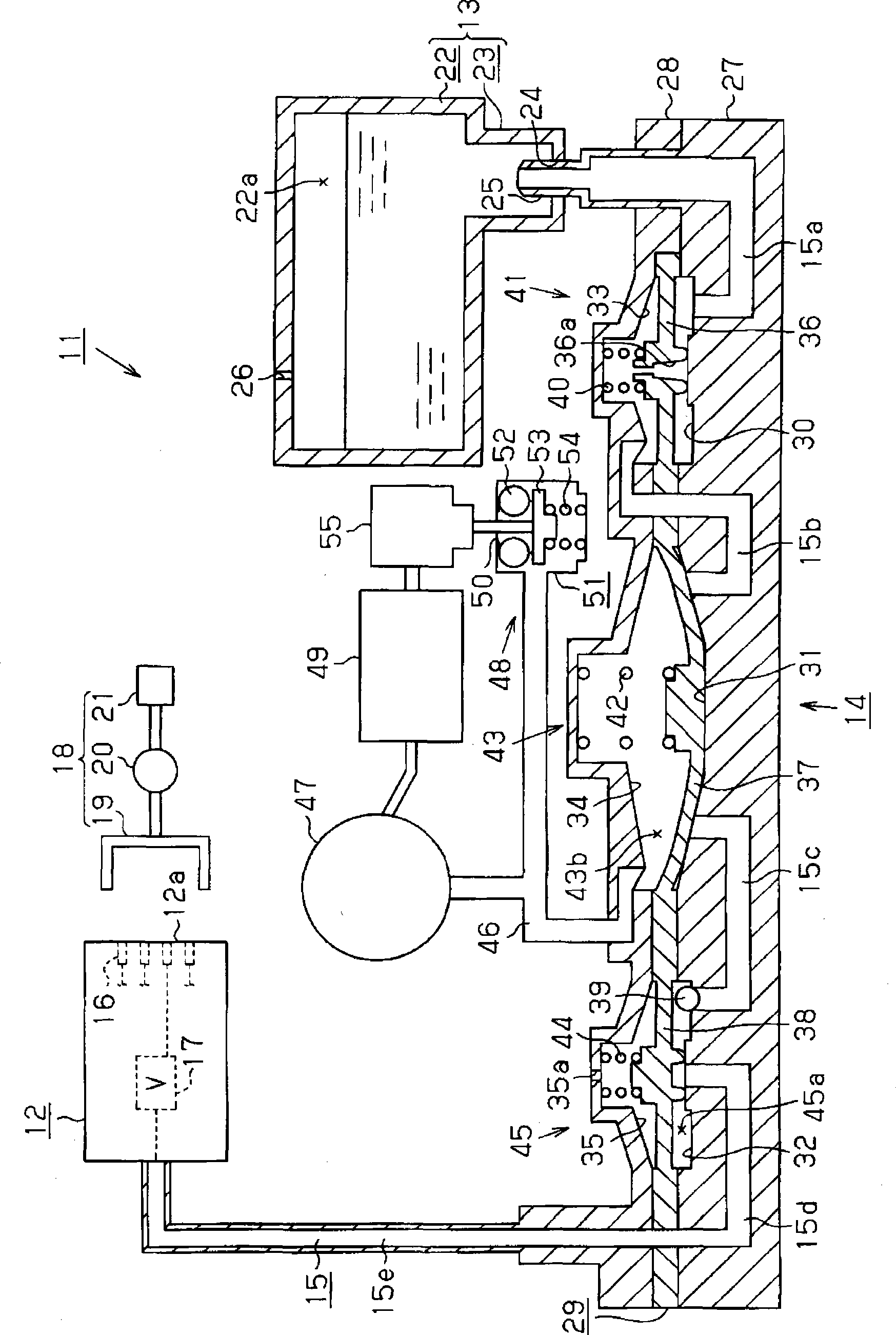
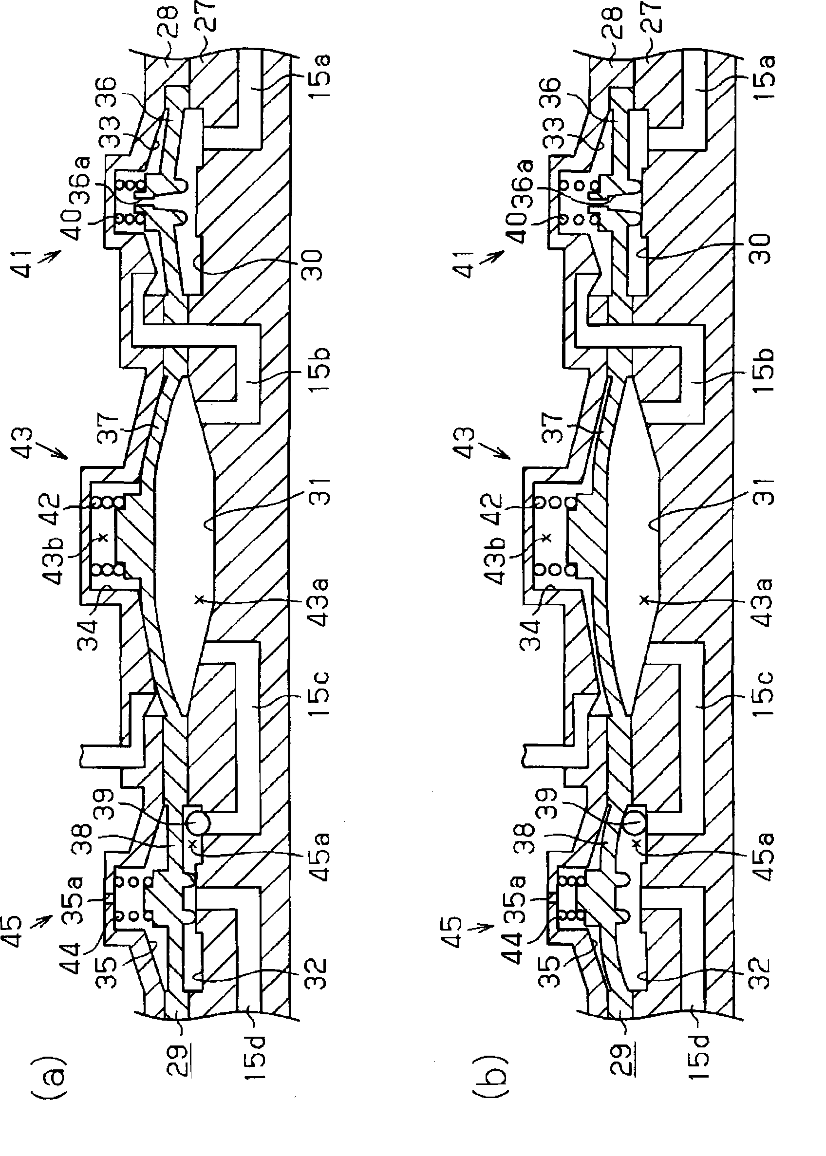
[0041] Below, refer to Figure 1 ~ Figure 3 Next, a first embodiment of an inkjet recording device (hereinafter referred to as a printer) that embodies the present invention as a type of liquid ejecting device will be described.

[0042] Such as figure 1 As shown, the printer 11 of this embodiment has: a recording head 12 serving as a liquid ejecting head that ejects ink (liquid) to a target (not shown); An ink supply device 14 serving as a liquid supply device for ink. The ink supply device 14 is provided with an ink flow that supplies ink from the upstream side on the ink cartridge 13 side to the downstream side on the recording head 12 side in a state where the upstream end is connected to the ink cartridge 13 and the downstream end is connected to the recording head 12. path (liquid supply flow path) 15.

[0043] In addition, in the printer 11 , a plurality of ink supply devices 14 are provided corresponding to the number (type) of colors of ink used in the printer 11 ....

no. 2 approach

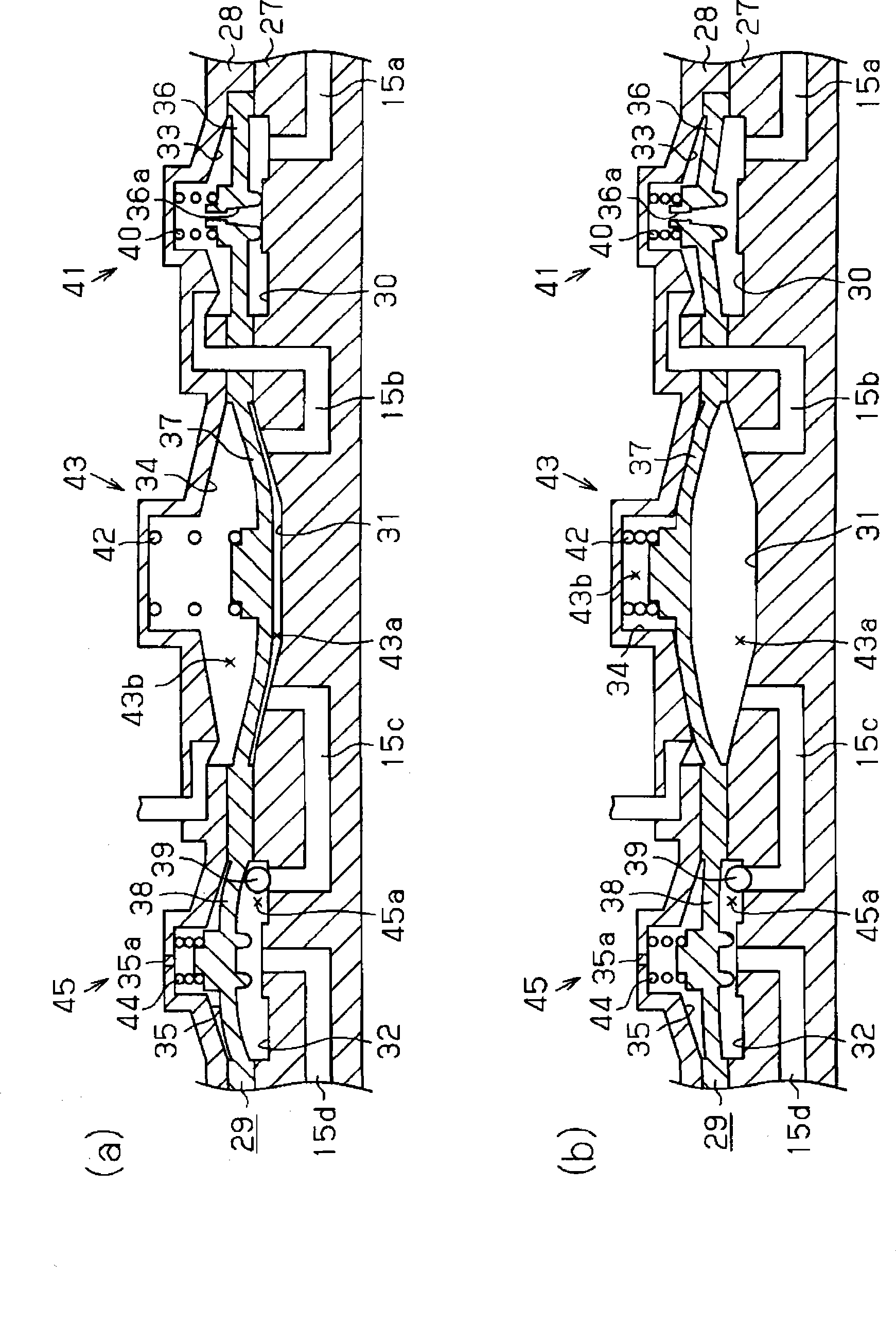
[0091] Below, refer to Figure 4 A second embodiment of the present invention will be described. However, since the second embodiment differs from the first embodiment only in that the shape of the suction side valve 41 is changed, and other structures are common, the same components are given the same reference numerals and detailed descriptions are omitted.

[0092] Such as Figure 4 As shown, when the suction-side valve body 36 of this embodiment is located at the top dead center position, the opening portion serving as the downstream end of the through-hole 36a abuts against the inner surface of the recess 33, and the through-hole 36a forming a part of the ink flow path 15 is closed. closed state (see Figure 4 (c)). And, in the surface of the outer surface of the suction side valve body 36 that faces the inner surface of the recessed part 33, there is formed an upstream valve body that is located at the top dead center position and is in contact with the inner surface ...


PUM


Abstract

The present invention relates to a liquid supplying device, capable of restraining mixture of gas into a liquid supply flow path when driving a pump for absorbing liquid into the liquid supply flow path from a liquid supply source, and maintaining the attraction efficiency of the pump well, and a liquid ejecting device having the liquid supplying device. The liquid supplying device includes a inksupplying flow path (15) that supplies ink from an upstream side as a ink box (13) toward a downstream side on which the ink is consumed; a pump (43) that is driven for changing the volume of a pump chamber that is a part of the ink supplying flow path (15); and a flow velocity reducing valve (41) that reduces the flow velocity of the ink passing through the ink supplying flow path (15) on the upstream side of the pump chamber by changing flow path resistance of the ink supplying flow path (15) in accordance with the speed of change of the volume of the pump chamber, in a case where the pump is driven for a suction operation that increases the volume of the pump chamber.

Description

technical field [0001] The present invention relates to a liquid supply device and a liquid ejection device that supply liquid from an upstream side serving as a liquid supply source side to a downstream side that consumes liquid. Background technique [0002] Conventionally, inkjet printers (hereinafter referred to as "printers") have been widely known as liquid ejecting devices that eject liquid to a target. This printer performs printing on a target recording medium by ejecting ink (liquid) supplied to a recording head (liquid ejection head) from nozzles formed on the recording head. Moreover, in such a printer, it has recently been proposed to have a device for pressurizing and supplying ink from the ink cartridge side to the recording head side in the way of connecting the ink flow path (liquid supply flow path) between the ink cartridge (liquid supply source) and the recording head. Carry out a pump-driven pump scheme. In this printer, if the pump chamber becomes neg...

Claims


Application Information

Patent Timeline
Patent Type & Authority Applications(China)
IPC IPC(8): B41J2/175
Inventor 横内秀弥
Owner SEIKO EPSON CORP
Why Eureka
Try Eureka