Unwinding assisting device and automatic winder comprising the same

An auxiliary device and winder technology, which is applied in the direction of transportation and packaging, delivery of filamentous materials, thin material processing, etc., can solve the problems of complicated electrical wiring arrangement of stepping motors, easy loosening, impact, etc., to achieve The effect of shortening the cycle time

Active Publication Date: 2009-06-24
MURATA MASCH LTD
View PDF1 Cites 19 Cited by
  • Summary
  • Abstract
  • Description
  • Claims
  • Application Information

AI Technical Summary

Problems solved by technology

However, since the air cylinder is a structure that drives the piston rod with considerable weight to move forward and backward, if the speed when returning to the original position is too high, the large inertial force will exert an impact on each part of the device, which may cause failure. reason
Furthermore, in terms of the structure of the device, since the installation space of the air cylinder needs to be roughly twice the length of the movement distance of the limiting member, it is difficult to reduce the size of the device.
[0007] In addition, since the structure in Japanese Patent Application Laid-Open No. 8-198520 is that the stepping motor itself as the driving device rises and falls together with the lifting guide (restricting member), therefore, the holding member supporting the stepping motor also needs a certain degree of strength. It is a structure that must be able to lift a large weight
Therefore, there is still room for improvement from the viewpoints of smooth lifting control, energy saving, and shock prevention.
Moreover, since the stepping motor moves up and down, the arrangement of the electrical wiring of the stepping motor is also complicated.
[0008] In addition, in the case where the vertical movement of the lifting guide is performed by a rack and pinion mechanism, the gears are configured in consideration of backlash, so looseness is likely to occur, and it is difficult to precisely position the lifting guide.
Moreover, in the case where the elevating guide is raised and lowered together with the rack assuming that one side of the stepping motor is fixed, since the space for the movement of the rack needs approximately twice the length of the moving distance of the elevating guide, it is not necessary to Sufficient miniaturization possible
In addition, when oiling the meshing portion of the rack and pinion, it is easy to attach fly to this portion due to unwinding of the yarn, etc., and the accumulation of fly may cause failure.
Also, maintenance work to remove the fly that adheres firmly to the oiled part takes a lot of time

Method used


Image

  • Unwinding assisting device and automatic winder comprising the same
  • Unwinding assisting device and automatic winder comprising the same
  • Unwinding assisting device and automatic winder comprising the same

Examples


Embodiment Construction

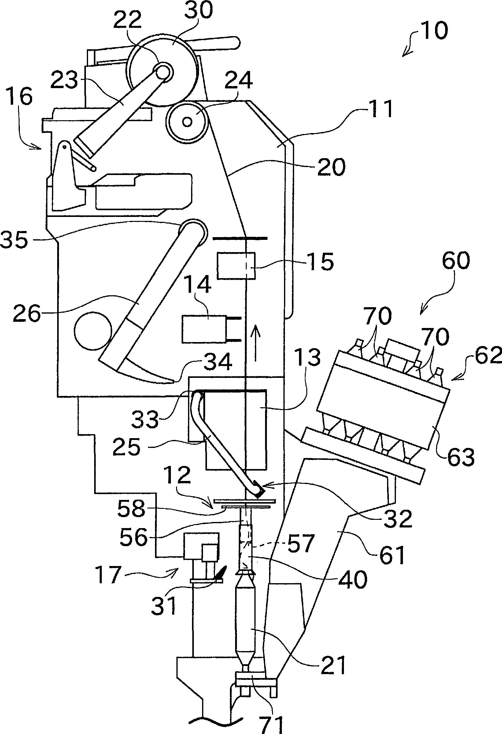
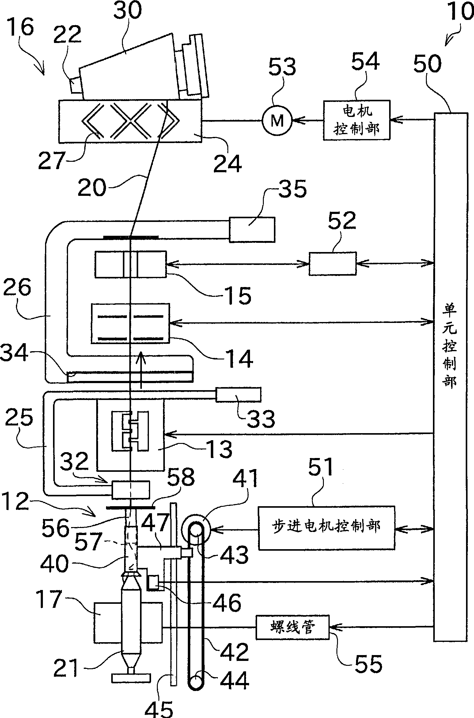
[0023] Next, preferred embodiments of the present invention will be described with reference to the drawings. figure 1 It is a side view of the winder unit 10 included in the automatic winder according to one embodiment of the present invention. figure 2 It is a front view schematically showing the structure of the winder unit 10 .

[0024] figure 1 with figure 2 The winder unit 10 shown is a device that traverses the yarn 20 unwound from the yarn supplying bobbin 21 on the winding bobbin 22 to form a package 30 of a predetermined shape with a predetermined length. The automatic winder of this embodiment includes a plurality of winder units 10 arranged in parallel, and a machine control device (not shown) arranged at one end in the parallel direction.

[0025] Each winder unit 10 has a unit frame 11 ( figure 1 ) and the winding unit main body 16 arranged on the side of the unit frame 11.

[0026] The winding unit main body 16 has a cradle 23 capable of holding the windi...


PUM


Abstract

The present invention relates to an unwinding assisting device for an automatic winder. The unwinding assisting device (12) includes a regulating member (40) that regulates a balloon generated when a yarn is unwound from a yarn supplying bobbin (21), and an elevating and lowering means for elevating and lowering the regulating means (40). The elevating and lowering means comprises a stepping motor (41) and a belt member (42) that transmits driving of the stepping motor (41). The belt member (42) is composed of a toothed belt.

Description

technical field [0001] The present invention relates to an automatic yarn winder, in particular to an unwinding auxiliary device for limiting balloons generated when unwinding yarn from a yarn feeding bobbin. Background technique [0002] Conventionally, there is known an automatic winder configured to include an unwinding assisting device for restricting a balloon generated when a yarn is unwound from a yarn supplying bobbin. The above-mentioned unwinding assisting device lowers the restricting member simultaneously with the lowering of the unwinding point of the yarn from the yarn supplying bobbin, and controls the formation of the balloon by maintaining a constant distance from the unwinding point. [0003] The structure of this kind of unwinding auxiliary device is mostly: a sensor for detecting the upper end position of the yarn being unwound and a lifting mechanism for lifting the limiting mechanism. By controlling the lifting mechanism such as an air cylinder or a ste...

Claims


Application Information

Patent Timeline
Patent Type & Authority Applications(China)
IPC IPC(8): B65H57/22B65H54/36B65H54/22
CPCB65H57/26B65H57/22B65H2701/31B65H57/12
Inventor 中川隆
Owner MURATA MASCH LTD
Why Eureka
Try Eureka