Radiating device

A heat dissipation device and heat absorbing plate technology, which is applied in cooling/ventilation/heating transformation, electrical components, electric solid devices, etc., can solve the problems of increased overall thickness of the heat dissipation device, inability to adapt to thinner and thinner electronic devices, and inability to install

Inactive Publication Date: 2012-07-25
FU ZHUN PRECISION IND SHENZHEN +1
View PDF0 Cites 0 Cited by
  • Summary
  • Abstract
  • Description
  • Claims
  • Application Information

AI Technical Summary

Problems solved by technology

However, this kind of gap will increase the overall thickness of the heat sink, making it impossible to be installed in thinner electronic devices, and unable to meet the needs of today's thinner and lighter electronic devices

Method used


Image

  • Radiating device
  • Radiating device
  • Radiating device

Examples


Embodiment Construction

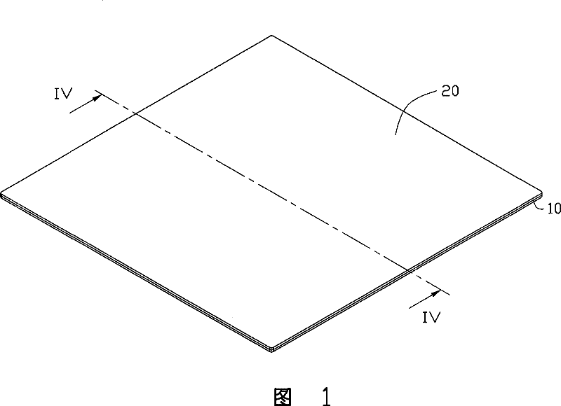
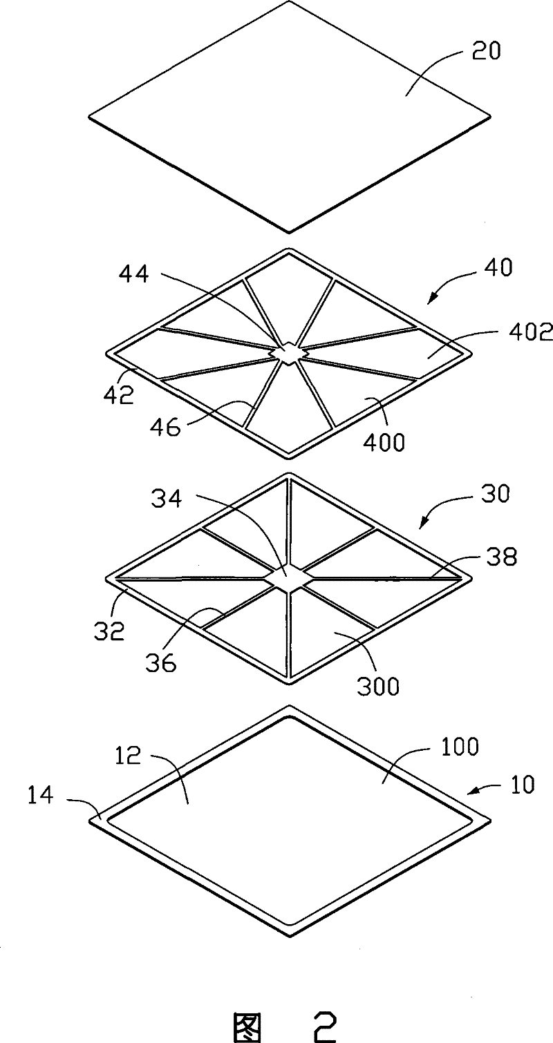
[0013] Such as Figures 1 to 2 As shown, the heat dissipation device of the present invention is a phase change heat dissipation device, which is used for dissipating heat from electronic components (not shown) installed in an electronic device (not shown). The heat dissipation device includes a heat absorbing plate 10, a heat releasing plate 20 fixed on the heat absorbing plate 10, a working fluid (not shown) accommodated between the heat absorbing plate 10 and the heat releasing plate 20, and a sandwich The capillary structure between the heat absorbing plate 10 and the heat releasing plate 20 (not shown).

[0014] The heat absorbing plate 10 includes a square accommodating portion 12 and a folded edge 14 horizontally extending outward from the top of the accommodating portion 12 . A square chamber 100 is defined in the accommodating portion 12 for accommodating working fluid. The middle area of ​​the bottom surface of the accommodating portion 12 is used to contact the el...


PUM


Abstract

Disclosed is a heat-dissipating device, which comprises a heat-dissipating plate; and the heat-dissipating plate is provided a cavity chamber used for containing the working fluid. A heat-dissipating plate is connected on a heat-absorbing plate and is used for sealing the cavity chamber; a capillary structure is formed in the cavity chamber, the capillary structure comprises a first capillary layer with a plurality of the first hollow cavities, and a second capillary layer with a plurality of the second hollow cavities; and the first hollow cavities are communicated with the second hollow cavities so as to contain the working fluid together. Compared with prior art, the plurality of the first and second communicated hollow cavities are arranged on the capillary structure of the heat-dissipating device, the size thereof is further bigger than that of the capillary porosities of the capillary structure, so as to lead the enough fluid to be contained into the cavities. Therefore, the corresponding gap is not necessary to be left by the first capillary layer and the second capillary layer; and the thickness of the heat-dissipating device can be controlled within a smaller range.

Description

technical field [0001] The invention relates to a cooling device, in particular to a phase change cooling device for cooling electronic components. Background technique [0002] Electronic components usually generate a lot of heat during operation. To ensure the normal operation of electronic components, the heat needs to be dissipated in time. For this reason, a cooling device is usually installed on the electronic components. The heat dissipation device usually includes a heat absorption plate and heat dissipation fins arranged on the heat absorption plate. The heat absorbing plate is made of metal materials with good thermal conductivity such as copper and aluminum, but the metal plate is limited by the limited thermal conductivity of the material itself. If it is an electronic component with high heat generation, it will produce obvious thermal resistance and cannot achieve good heat dissipation. Affect the operational stability of electronic components. [0003] In o...

Claims


Application Information

Patent Timeline
Patent Type & Authority Patents(China)
IPC IPC(8): H05K7/20H01L23/427
Inventor 赖振田周志勇丁巧利
Owner FU ZHUN PRECISION IND SHENZHEN
Why Eureka
Try Eureka