High-pressure discharge lamp with an improved starting capability, as well as a high-voltage pulse generator

A technology of high-pressure discharge lamps and pulse generators, applied in the direction of discharge lamps, gas discharge lamps, parts of gas discharge lamps, etc., can solve the problems of being unable to be heated, and achieve the effect of easy breakdown and compact structure

Inactive Publication Date: 2009-06-24
OSRAM GMBH
View PDF6 Cites 0 Cited by
  • Summary
  • Abstract
  • Description
  • Claims
  • Application Information

AI Technical Summary

Problems solved by technology

Currently commonly used ignition devices usually cannot be heated above 100°C

Method used


Image

  • High-pressure discharge lamp with an improved starting capability, as well as a high-voltage pulse generator
  • High-pressure discharge lamp with an improved starting capability, as well as a high-voltage pulse generator
  • High-pressure discharge lamp with an improved starting capability, as well as a high-voltage pulse generator

Examples


Embodiment Construction

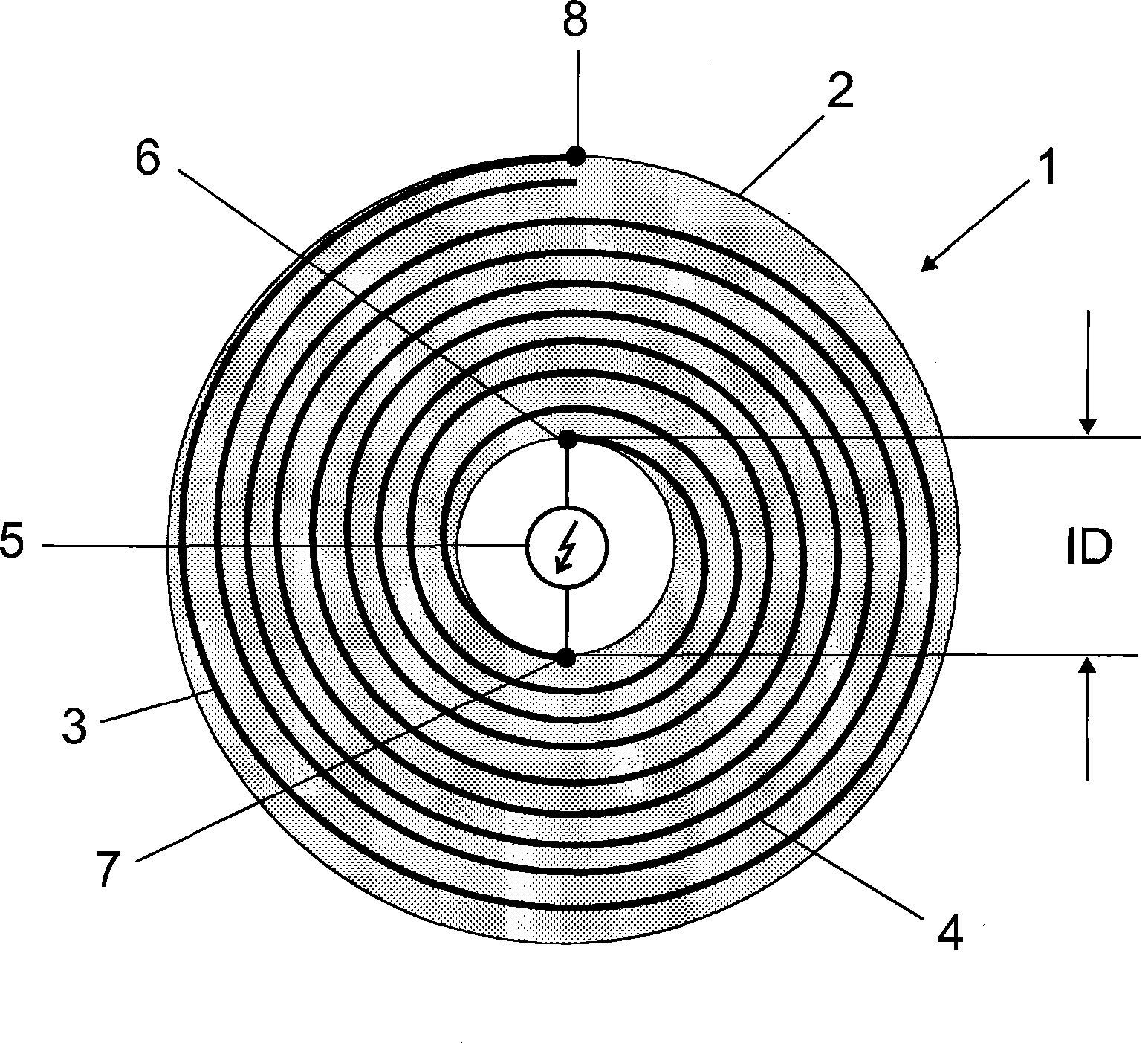
[0028] figure 1 The structure of the helical pulse generator 1 is shown in plan view. The helical pulse generator comprises a ceramic cylinder 2 into which two different metallic conductors 3 and 4 are helically wound as foil strips. The cylinder 2 is hollow inside and has a given inner diameter ID. The two inner contacts 6 and 7 of the two conductors 3 and 4 lie approximately opposite each other and are connected to each other via a spark arrestor 5 .

[0029] Only the outer conductor of the two conductors has another contact 8 at the outer edge of the cylinder. The other conductor ends open. Thus, the two conductors together form a waveguide in a dielectric medium (ceramic).

[0030] Helical pulse generators are wound from two ceramic discs coated with metal paste or constructed from two metal discs and two ceramic discs. An important characteristic parameter here is the number of turns n, which should preferably be in the order of magnitude of 5 to 100. The winding ar...


PUM


Abstract

A spiral pulse generator is used to start a high-pressure discharge lamp and is accommodated directly in the external bulb of the lamp. The spiral pulse generator comprises two parts which are manufactured jointly as an LTCC component.

Description

technical field [0001] The invention is based on a high-pressure discharge lamp according to the preamble of claim 1 . Such lamps are in particular high-pressure discharge lamps for general lighting or for photographic purposes. Furthermore, the invention relates to a high-voltage pulse generator which can be used in particular for a lamp. Background technique [0002] The ignition problem of high-pressure discharge lamps is currently solved by integrating the ignition device into the ballast. The disadvantage is that the feeder must be designed to withstand high voltage. [0003] Attempts have been made repeatedly in the past to integrate the ignition unit into the lamp. In such cases an attempt was made to integrate the ignition unit into the lamp head. A particularly efficient and high-pulse ignition is achieved by means of so-called helical pulse generators (cf. US-A 3 289 015). Such devices have long been proposed in various high-pressure discharge lamps, such as m...

Claims


Application Information

Patent Timeline
Patent Type & Authority Applications(China)
IPC IPC(8): H05B41/04H01J61/00H03K5/00
CPCH01J61/34H01J61/56H01J61/547H05B41/042
Inventor 安德烈亚斯·克洛斯
Owner OSRAM GMBH
Why Eureka
Try Eureka