Torque wrench with control unit

A control unit, torque wrench technology, applied in the field of wrenches

Inactive Publication Date: 2009-07-01
STANLEY CHIRO INT
View PDF0 Cites 10 Cited by
  • Summary
  • Abstract
  • Description
  • Claims
  • Application Information

AI Technical Summary

Problems solved by technology

[0010] The purpose of the present invention is to overcome the defects of the existing torque wrench ...

Method used


Image

  • Torque wrench with control unit
  • Torque wrench with control unit
  • Torque wrench with control unit

Examples


Embodiment Construction

[0048] In order to further explain the technical means and effects of the present invention to achieve the intended purpose of the invention, the specific implementation, structure, characteristics and details of the torque wrench with a control unit proposed according to the present invention will be described below in conjunction with the accompanying drawings and preferred embodiments. Its effect is described in detail below.

[0049] The aforementioned and other technical contents, features and effects of the present invention will be clearly presented in the following detailed description of preferred embodiments with reference to the drawings. For convenience of description, in the following embodiments, the same elements are denoted by the same numbers.

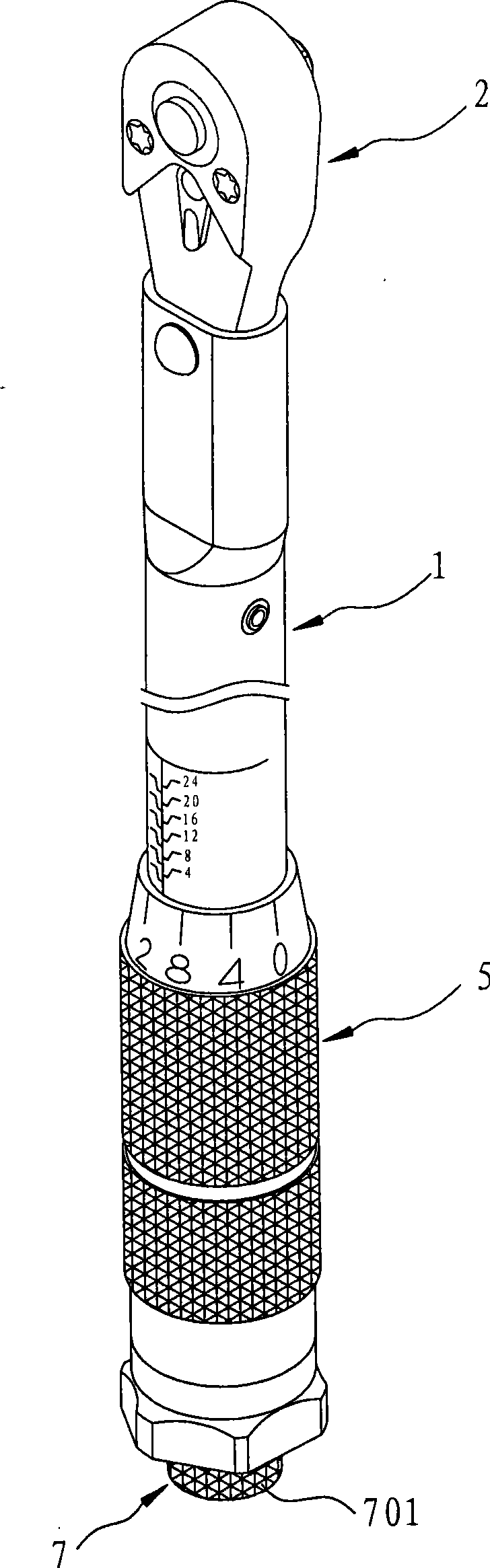
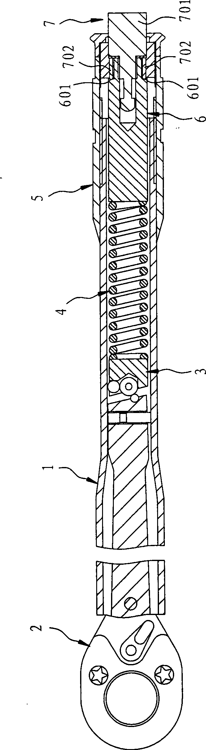
[0050] see image 3 , Figure 4 , Figure 5 as shown, image 3 It is a three-dimensional schematic diagram of the appearance of a first preferred embodiment of a torque wrench with a control unit in the present inv...


PUM


Abstract

The invention relates to a torque force spanner provided with a control unit, which comprises a body unit, a handle unit which is rotatably arranged on a pipe part and provided with at least one actuating hole and one clamping hole, a control ring, an elastic element arranged between the control ring and the handle unit, and at least one control unit, wherein the pipe part is provided with a plurality of shallow grooves; the control ring is provided with an inner annular surface, at least one abdicating groove which is concavely arranged on the inner annular surface and two positioning grooves which are concavely arranged on the inner annular surface; and the elastic element is provided with a first end part which presses a limit piece on the pipe part, a clamping part which is clamped with the clamping hole and a positioning part. When the control ring is at a first position, the abdicating groove is corresponding to the first end part, the inner annular surface is away from the first end part, and the positioning part is connected with one of the positioning grooves; and when the control ring is at a second position, the abdicating groove is separated from the first end part, the inner annular surface is close to the first end part, and the positioning part is connected with the other positioning groove. Through the rotary switch of the control ring of the control unit, the torque force spanner not only has the advantages of convenient and fast operation and definite positioning, but also can prevent the control unit from accidentally breaking.

Description

technical field [0001] The invention relates to a wrench, in particular to a torque wrench with a control unit which is not only easy to operate, fast and has clear positioning by means of the rotation switching of the control ring of the control unit, but also prevents the control unit from being accidentally broken. Background technique [0002] see figure 1 , figure 2 as shown, figure 1 It is a three-dimensional schematic diagram of the appearance of an existing wrench with preset locking torque value, figure 2 It is a partial sectional view of the combined structure of the existing wrench. An existing wrench that can preset the locking torque value includes a pipe fitting 1, a wrench 2 that is pivotally connected to the pipe fitting 1 and aligns with the pipe fitting 1 under normal conditions, and a wrench installed in the pipe fitting 1. And the actuating block 3 abutting against the end of the wrenching member 2, a compression spring 4 abutting against the actuat...

Claims


Application Information

Patent Timeline
IPC IPC(8): B25B23/14B25B23/16B25B23/00
Inventor 刘圳雄
Owner STANLEY CHIRO INT
Why Eureka
Try Eureka