Rapid and efficient filtering whole blood in a capillary flow device

A capillary, filter cartridge technology for use in the field of lateral flow filter elements

Active Publication Date: 2009-07-01
MICROPOINT BIOTECHNOLOGIES CO LTD
View PDF2 Cites 4 Cited by
  • Summary
  • Abstract
  • Description
  • Claims
  • Application Information

AI Technical Summary

Problems solved by technology

The problem with this single-filter technology is that the same filter that handles t

Method used


Image

  • Rapid and efficient filtering whole blood in a capillary flow device
  • Rapid and efficient filtering whole blood in a capillary flow device
  • Rapid and efficient filtering whole blood in a capillary flow device

Examples


Embodiment

[0045] The following examples illustrate, but do not limit the claimed invention.

[0046] Example 1 - Sidestream Filter in a Cartridge

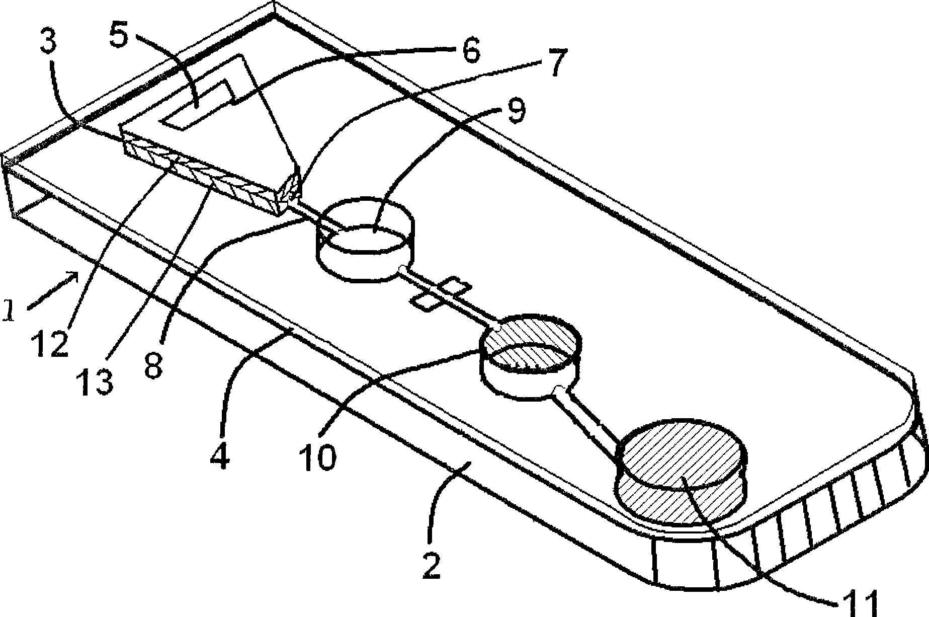
[0047] Preparation of assay filter cartridges incorporating a lateral flow filtration system with gradient pore sizes. Such filter cartridges efficiently deliver filtered slurries to assay systems with low dead volume and high flow rates without the need for external force.

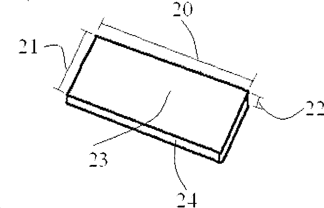
[0048] The filter cartridge uses two asymmetric gradient filters. A suitable asymmetric filter is the Pall BTS-SP-300 GR (eg image 3 ) or similar with a thickness of 300um. To avoid excessive sample volume requirements, it is not recommended to stack two or more asymmetric filters with the same pore size just to increase the filter channel length. Such a configuration can retain whole blood or serum between filter layers due to the capillary stop action of the larger pore size in the fluid channel. For example, stacking two BTS-SP-300 GR layers does not increase...


PUM


Abstract

This invention provides lateral flow filters with pore size gradients and with features to prevent peripheral flows around the filter. The filters can be laminated composites of two or more planar filter layers. Cartridges employing the filters can include a filtration chamber configured to retain the lateral flow filters including a port for sample application and a capillary channel for filtrate egress. The fluid egress port can be positioned to receive filtrate from one filter layer but not another.

Description

technical field [0001] The present invention relates to side flow filter elements and filter cartridges using such filter elements to separate particulates from suspension samples. The filter may include a flow along the length of the planar filter that flows into the capillary channels after filtration. The filter may be two or more filter elements stacked, for example, having larger pores at the point of sample application relative to the filtrate outlet area. Background technique [0002] Biological samples are often required for diagnostic testing, such as whole blood or urine, which include large amounts of particulate matter that can clog microchannels of assay devices and interfere with reaction and detection systems. To avoid the problem of particulates in clinical samples, particulates are typically centrifuged or removed by filtration prior to sample analysis. [0003] Prior art particulate removal by filtration has largely focused on forced transverse flow mecha...

Claims


Application Information

Patent Timeline
IPC IPC(8): G01N1/34G01N33/48
CPCG01N33/491
Inventor 张囡万志良哈沙尔·西拉恩加利卡
Owner MICROPOINT BIOTECHNOLOGIES CO LTD
Why Eureka
Try Eureka