

Temperature equalization board
A technology of temperature uniformity plate and bottom plate, applied in cooling/ventilation/heating transformation, electrical components, electric solid-state devices, etc., can solve the problems affecting the normal operation of heating electronic components, temperature rise, etc., to improve heat transfer efficiency, reduce Overall thickness, the effect of reducing resistance
- Summary
- Abstract
- Description
- Claims
- Application Information
AI Technical Summary
Problems solved by technology
Method used
Image

Examples
Embodiment Construction
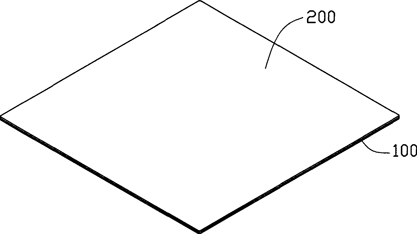
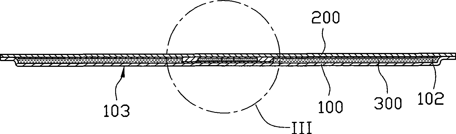
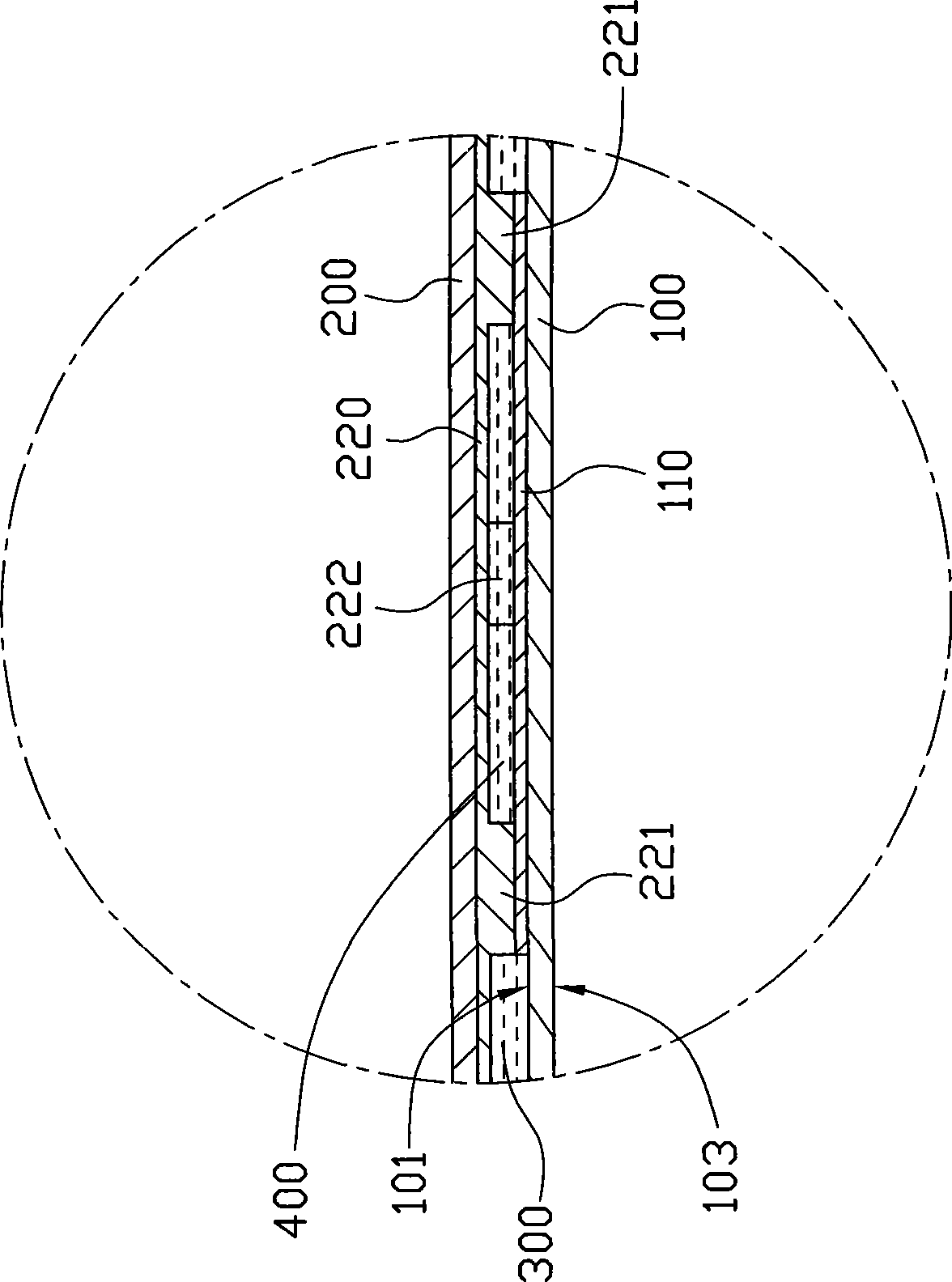
[0015] Such as figure 1 and Figure 4 Shown is the first embodiment of the temperature chamber of the present invention. The temperature chamber includes a bottom plate 100 with a concave cavity 102 and a cover plate 200, the cover plate 200 is set on the bottom plate 100 and seals the concave cavity 102 on the bottom plate 100 to form a chamber (not shown in the figure) , the chamber is pumped into a low pressure and filled with a phase-change working medium such as water, ethanol, paraffin, etc. The temperature chamber also includes a first capillary structure 220 disposed on the inner surface 201 of the cover plate 200 , a second capillary structure 221 disposed in the chamber, and a third capillary structure disposed on the inner surface 101 of the bottom plate 100 . The structure 110, the first gaseous working medium flow space 300 surrounding the periphery of the second capillary structure 221 and a second gaseous working medium flow space 400 formed inside the second ...
PUM
 Abstract
Description
Claims
Application Information