Automatic intervention device of catheter

A catheter and automatic technology, applied in the direction of catheters, etc., can solve problems such as difficult feedback, short motor life, and slippage, and achieve the effects of high efficiency, lower proficiency requirements, and high precision

Inactive Publication Date: 2009-07-08
HARBIN INST OF TECH
View PDF0 Cites 21 Cited by
  • Summary
  • Abstract
  • Description
  • Claims
  • Application Information

AI Technical Summary

Problems solved by technology

[0003] The purpose of the present invention is to solve the problems of difficult force feedback and slippage in the existing continuous conveying device, while the motor needs to be frequently alternated in positive and negative directions during the operation of the intermittent conveying device, the life of the motor is short, and the catheter cannot be replaced automatically. Automated Catheter Intervention Device

Method used


Image

  • Automatic intervention device of catheter
  • Automatic intervention device of catheter
  • Automatic intervention device of catheter

Examples


specific Embodiment approach 1

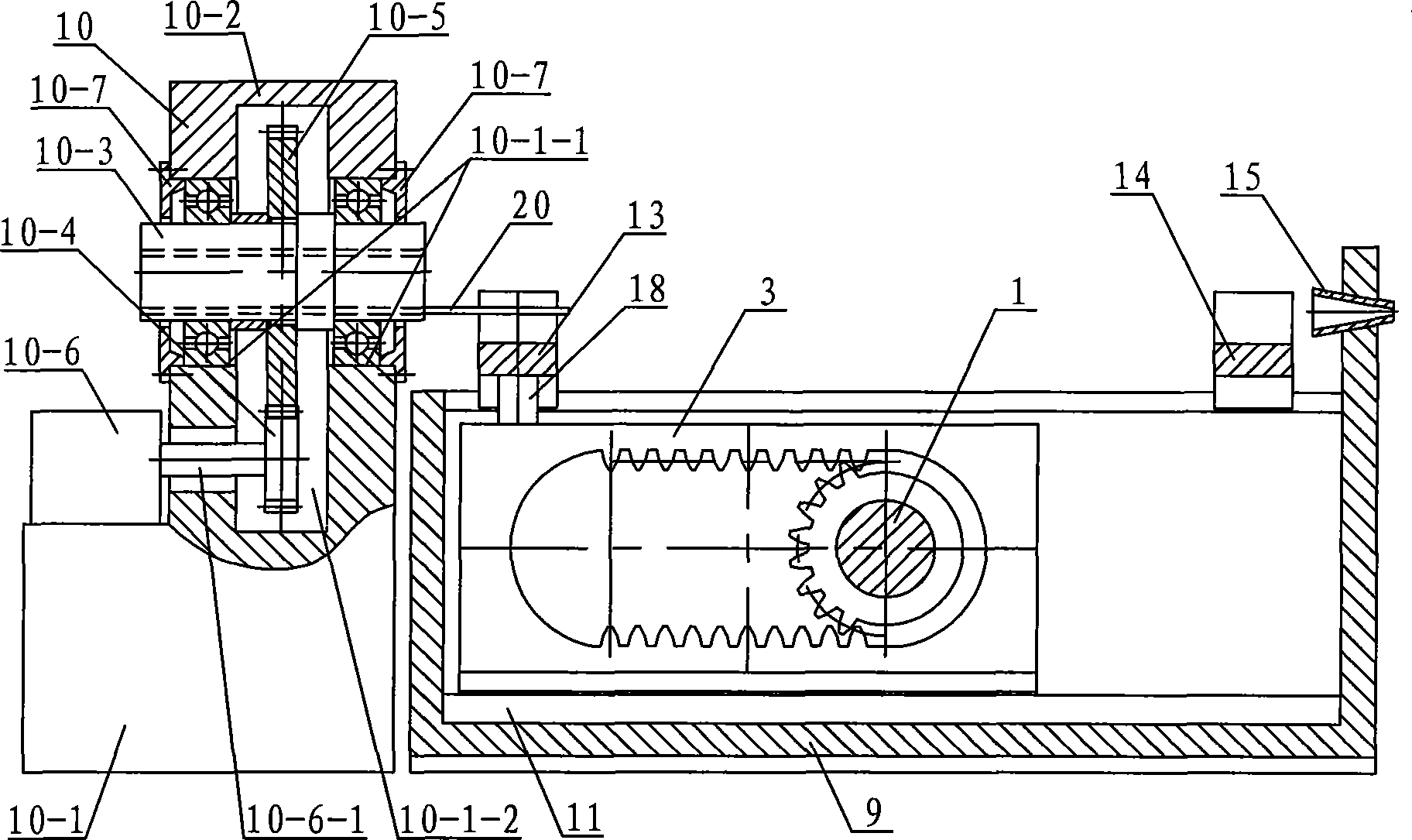
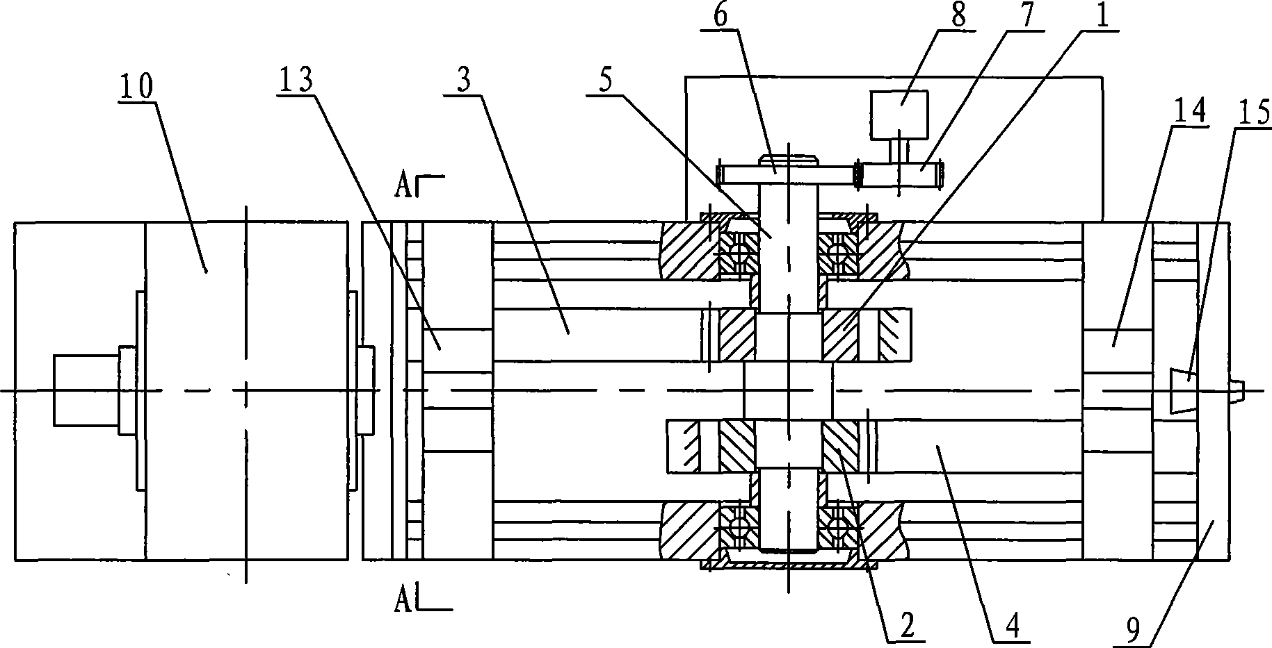
[0007] Specific implementation mode one: combine Figure 1 ~ Figure 4 Describe this embodiment. This embodiment includes a first half gear 1, a second half gear 2, a first double rack 3, a second double rack 4, a shaft 5, a driven gear 6, a driving gear 7, and a DC motor 8 , box body 9, tube changing mechanism 10, first fixed rail 11, second fixed rail 12, first jaw mechanism 13, second jaw mechanism 14, catheter sheath 15, two jaw fixing rails 17, first The connecting plate 18 and the second connecting plate 19, the driven gear 6 meshes with the driving gear 7, the driving gear 7 is arranged on the output shaft of the DC motor 8, and the first fixed rail 11 and the second fixed rail 12 are longitudinally symmetrically mounted on the case. On the bottom plate of the body 9, two jaw fixing rails 17 are symmetrically arranged on the outer sides of the first fixing rail 11 and the second fixing rail 12 and are fixedly connected with the bottom plate of the box body 9, and the dov...

specific Embodiment approach 2

[0008] Specific implementation mode two: combination Figure 5 ~ Figure 7 Describe this embodiment, the first jaw mechanism 13 of this embodiment and the second jaw mechanism 14 are all made of two half jaws 13-1, two armatures 13-2, two springs 13-3, the third fixed rail 13-4, jaw support plate 13-5, two fourth fixed rails 13-6, jaw bottom plate 13-7, two baffle plates 13-8, two force measuring strain gauges 13-9 and electromagnet 13 -10, the two half-claws 13-1 are arranged oppositely and the bottoms are respectively connected with the two armatures 13-2, and the dovetail tenons at the lower ends of the two armatures 13-2 are matched with the dovetail grooves at the upper end of the third fixed rail 13-4 , the third fixed rail 13-4 is arranged between the two jaw support plates 13-5 and the two ends are respectively connected to the two jaw support plates 13-5, each armature 13-2 is connected to the jaw support plate 13-5 5 is provided with a spring 13-3, one end of the spr...

specific Embodiment approach 3

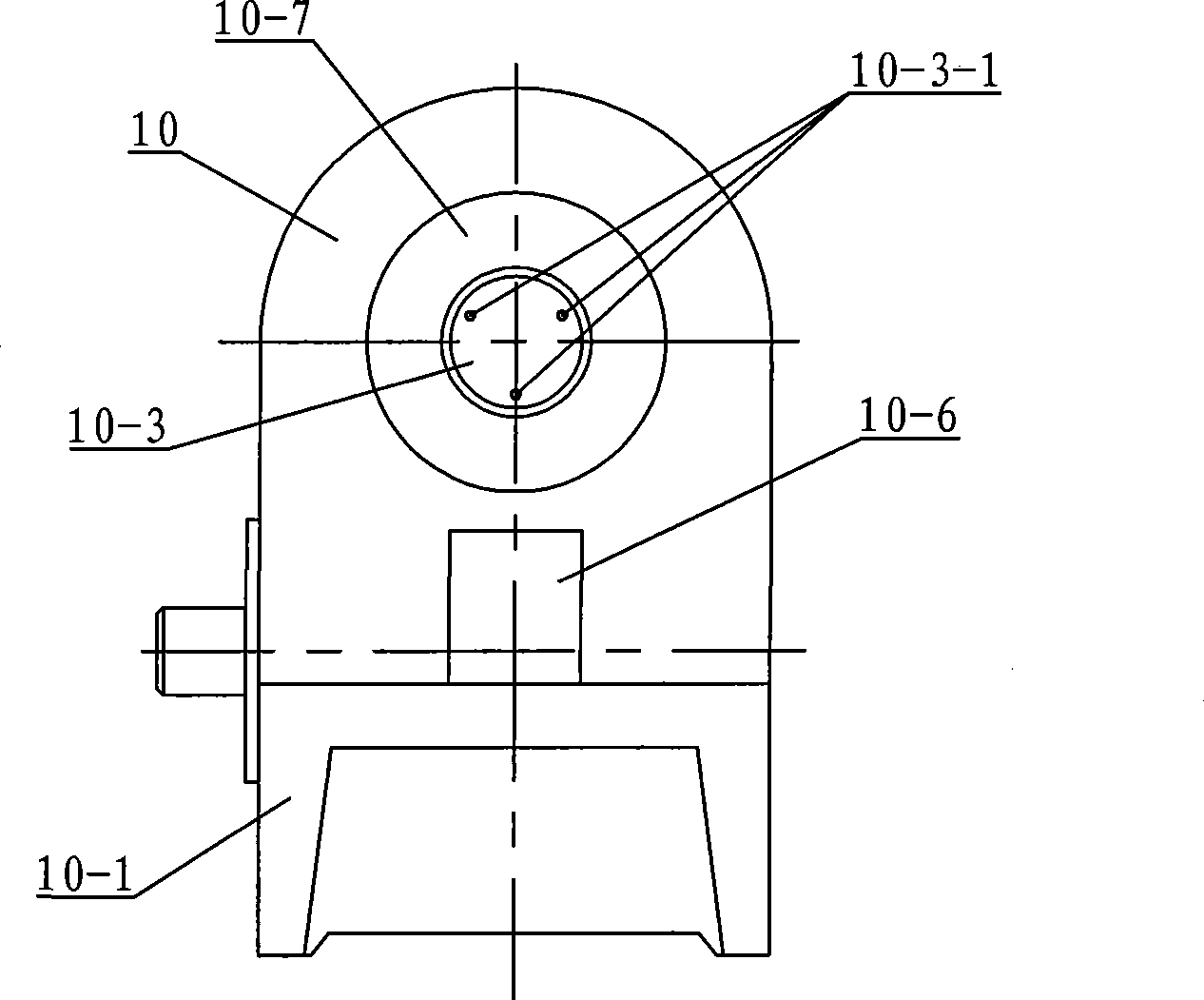
[0010] Specific implementation mode three: combination figure 1 Describe this embodiment, the pipe changing mechanism 10 of this embodiment consists of a base 10-1, an upper cover 10-2, a cylinder 10-3, a driving wheel 10-4, a driven wheel 10-5, a motor 10-6 and two A bearing cover 10-7 is composed, the upper cover 10-2 is arranged on the upper end of the machine base 10-1, and the upper end surface of the machine base 10-1 is provided with the wheel groove hole 10 communicating with the lower end surface of the upper cover 10-2. -1-2, the front and rear side walls of the loam cake 10-2 are respectively provided with a bearing mounting hole 10-1-1, the motor 10-6 is fixedly mounted on the support 10-1 and the output shaft on the motor 10-6 10-6-1 passes through the rear side wall of the upper cover 10-2 and is fixedly connected with the driving wheel 10-4, the driving wheel 10-4 meshes with the driven wheel 10-5, and the driven wheel 10-5 is installed in the cylinder 10-3 Abo...


PUM


Abstract

A conduit automatic intervention device relates to a conduit delivery mechanism. The conduit automatic intervention device solves the problems that the existing continuous mode delivery mechanism has difficult force feedback and has slippage; the motor of a batch-type delivery mechanism needs frequently positive inverted alternation. Two holding jaw fixed rails are symmetrically arranged on the outside of a first fixed rail and a second fixed rail. A dovetail at the lower end of a first double rack is matched with a dovetail groove of the first fixed rail. The dovetail at the lower end of a second double rack is matched with the dovetail groove of the second fixed tail. A first half gear and a second half gear are respectively arranged on a shaft, the two ends of which are articulated with the two holding jaw fixed rails. A first holding jaw mechanism is fixedly arranged on a first connection plate and a second holding jaw mechanism is fixedly arranged on a second connection plate. The centre line of a catheter sheath is superposed with the axle center of the first holding jaw mechanism and the second holding jaw mechanism. The axle center of a tunnel body of a tube replacing mechanism is superposed with the axle center of the first holding jaw mechanism and the second holding jaw mechanism. The conduit automatic intervention device realizes the continuous delivery of the conduit and avoids the frequency starting of the motor.

Description

technical field [0001] The invention relates to a catheter delivery device, in particular to an intervention device for automatically delivering catheters in minimally invasive interventional operations. Background technique [0002] Minimally invasive interventional surgery has been widely used in the world due to its advantages of less bleeding, less trauma, fewer complications, safety and reliability, and quick postoperative recovery. Catheter is the most important tool in interventional surgery. At present, catheter intervention is mainly delivered manually by doctors at the operation site. The disadvantages are: (1), the operation accuracy is not easy to grasp, and the trembling of the doctor's hands, elbows and shoulders will cause the distal end of the catheter to vibrate. (2) Doctors operate on the spot and inevitably suffer from radiation injuries. To avoid radiation, doctors need to wear heavy lead clothing. Therefore, the development trend of catheter interventio...

Claims


Application Information

Patent Timeline
Patent Type & Authority Applications(China)
IPC IPC(8): A61M25/082
Inventor 付宜利刘浩黄文泰颜增翼王树国
Owner HARBIN INST OF TECH
Why Eureka
Try Eureka