Cutting machine

A technology of cutting machine and turntable, which is applied in the direction of metal sawing equipment, sawing machine, metal processing equipment, etc. It can solve the problems of guide rail scratches, inconvenient locking operation, unreliable locking, etc., and achieve convenient setting and locking Easy to operate and good reliability

Inactive Publication Date: 2009-07-08
王骥
View PDF1 Cites 3 Cited by
  • Summary
  • Abstract
  • Description
  • Claims
  • Application Information

AI Technical Summary

Problems solved by technology

[0003] The object of the present invention is to provide a cutting machine with convenient setting position of the guide rail locking knob, convenient locking operation, reliable locking, and no scratches on the guide rail surface, which solves the limitation of the setting position of the guide rail locking handle in the prior art It may cause inconvenience in the locking operation. The contact surface between the end of the guide rail locking handle and the guide rail is small, and the locking is unreliable. At the same time, the guide rail locking handle is also likely to cause scratches on the surface of the guide rail, etc.
[0004] Another object of the present invention is to provide a cutting machine with simple structure, good reliability and convenient operation of the turntable positioning mechanism, which solves the problems of relatively complicated structure and poor reliability of the existing turntable locking device

Method used


Image

  • Cutting machine
  • Cutting machine
  • Cutting machine

Examples


Embodiment

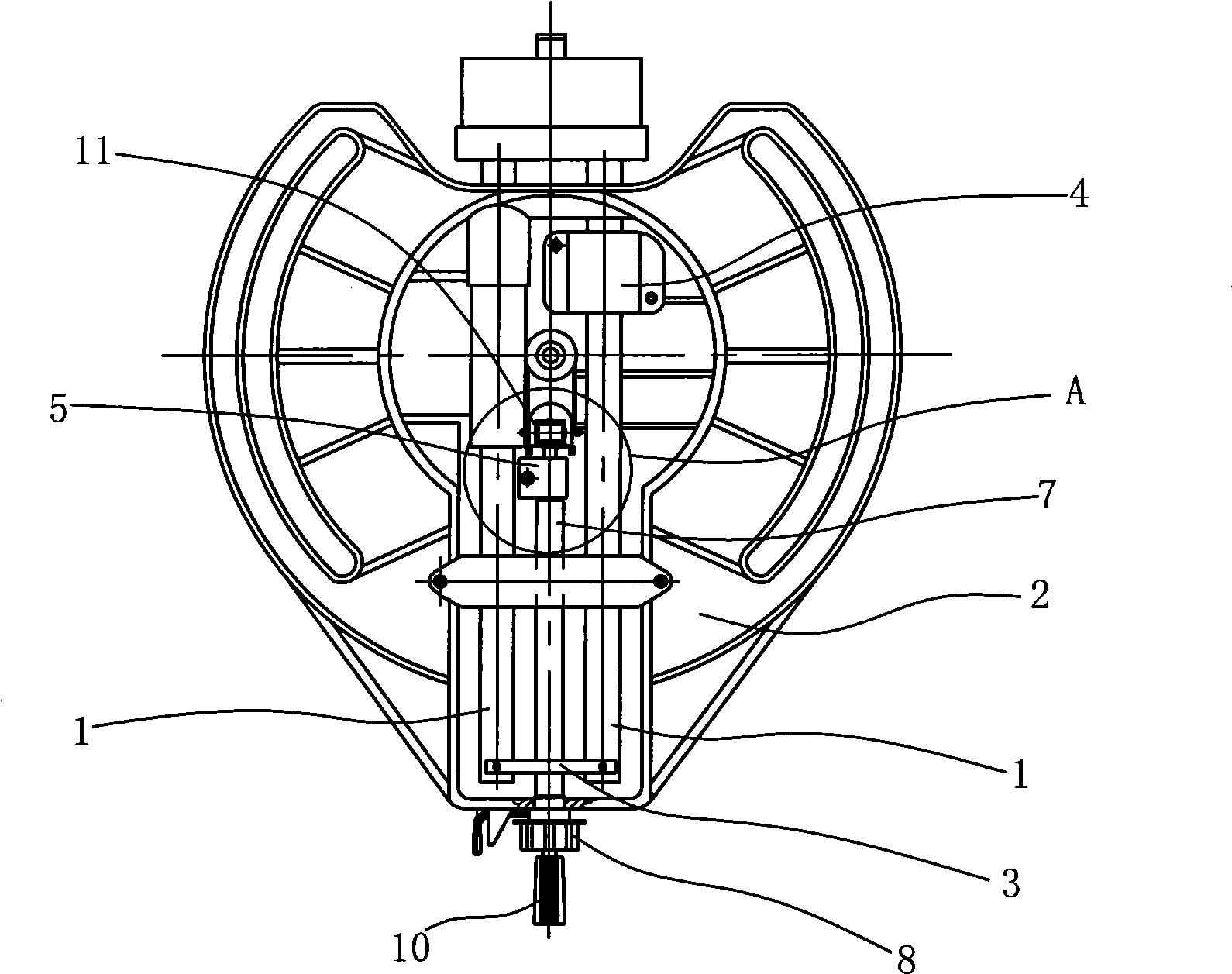
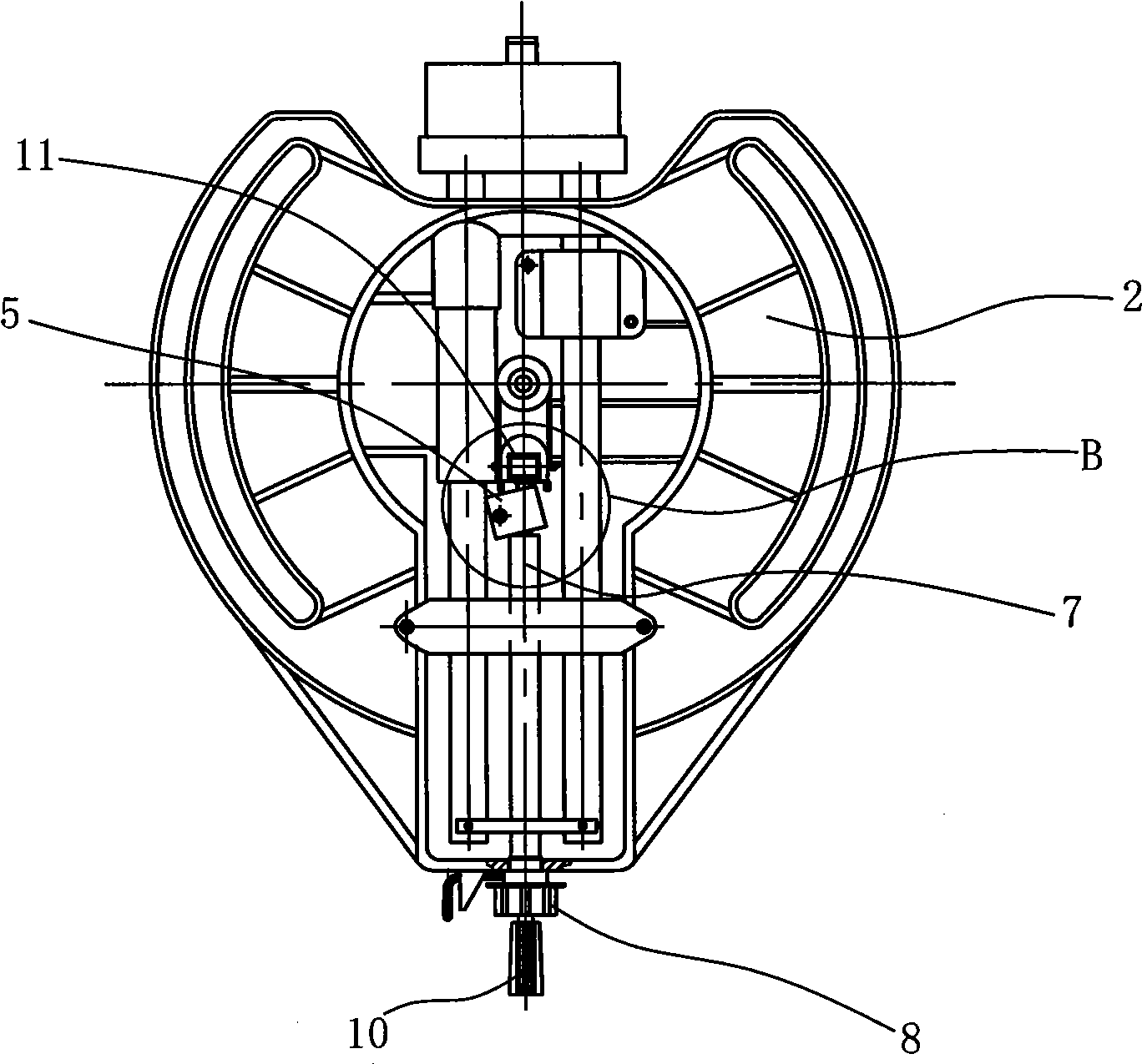
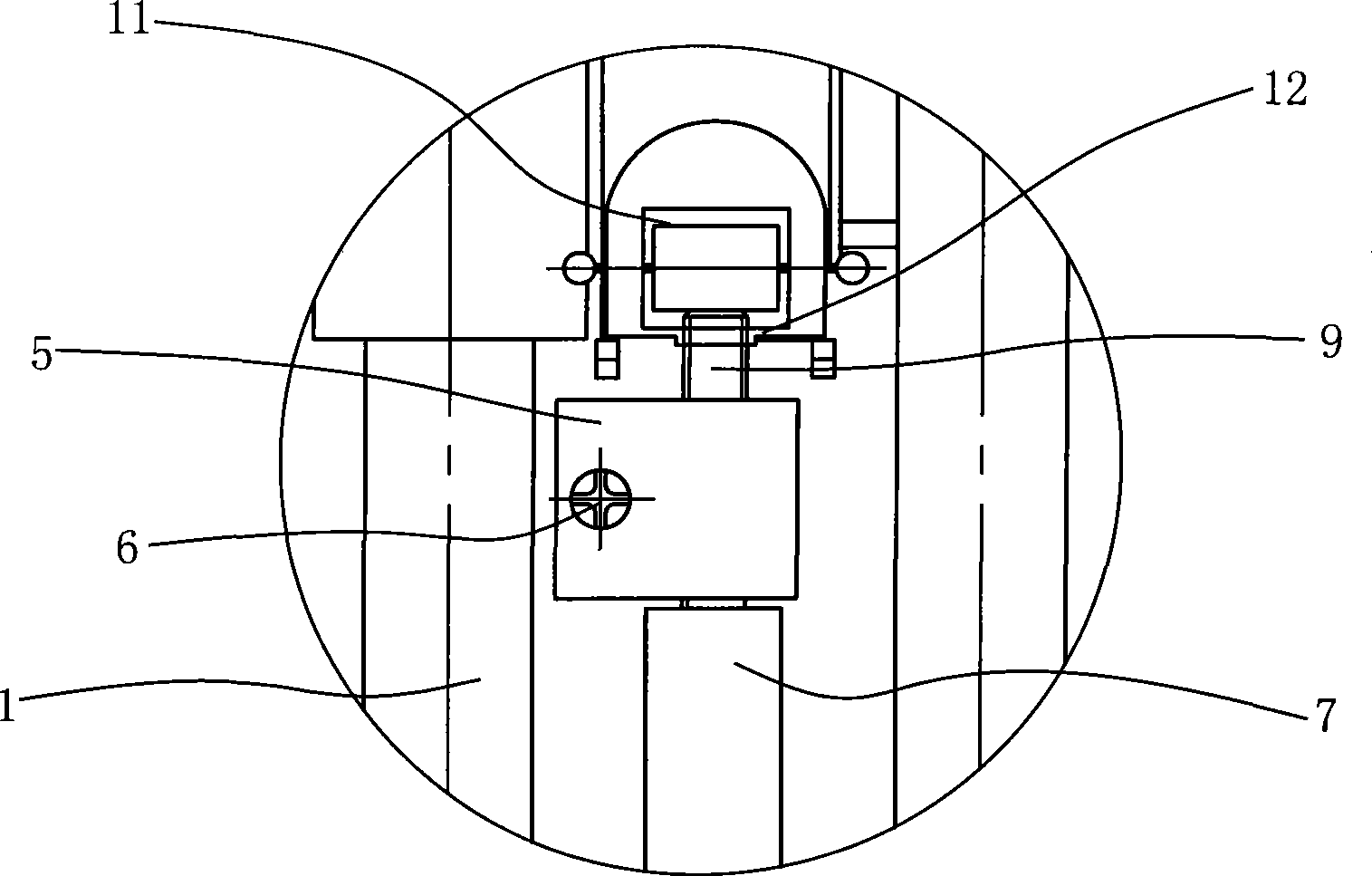
[0030] Embodiment: the turntable is connected to the base in rotation, and the cutting parts are slidingly connected to the turntable through guide rails, such as figure 1 , figure 2 , image 3 and Figure 4As shown, two parallel guide rails 1 are slidingly connected with the turntable 2, and a linkage plate 3 is connected between the two guide rails 1, and the linkage plate 3 and the two guide rails 1 are fixedly connected by screws respectively, and the turntable 2 is provided with a bearing seat 4. The bearing seat 4 and the turntable 2 are connected by screws. The bearing seat 4 is provided with a linear bearing, and the linear bearing and the bearing seat 4 are in interference fit, and the two guide rails 1 are matched with the linear bearing. One of the two guide rails 1 is provided with a guide rail lock block 5, the guide rail lock block 5 and the turntable 2 are hinged by step screws 6, the guide rail lock block 5 is in contact with one end of the actuating shaft 7...


PUM


Abstract

The invention relates to a cutting machine, in particular to the improved guideway locking structure and the turnplate locking structure of the cutting machine. A guideway locking piece is arranged near one of two guideways and is hinged with the turnplate; the guideway locking piece comes in contact with one end of a brake shaft, and the other end of the brake shaft comes in contact with the inner end of a guideway tight locking rotary knob which is in threaded connection with the turnplate; when the guideway tight locking rotary knob is tightly screwed, the brake shaft is pushed by the guideway tight locking rotary knob in a forward shaft direction, the front end of the brake shaft pushes the guideway locking piece to rotate so as to cause the guideway locking piece to tightly press the surface of the guideway, thereby relatively locking the guideway and the turnplate; and when the tight locking rotary knob is screwed to be loosened, the brake shaft loses the push force of the guideway tight locking rotary knob, the guideway locking piece is separated from the surface of the guideway to be reset, and the guideway and the turnplate can be relatively slid. The guideway tight locking rotary knob is convenient to be arranged, and the invention has the advantages of convenient locking operation, reliable locking and no surface scratch of the guideway.

Description

technical field [0001] The invention relates to a cutting machine, in particular to an improvement of a guide rail locking structure and a turntable locking structure of the cutting machine. Background technique [0002] A miter saw (patent number: CN200520117414.9), one end of the guide rail is connected to the bracket, and the other end is slidingly connected to the turntable. A guide rail locking ring is sleeved between the guide rail and the turntable, and the side wall of the guide rail locking ring A threaded through hole is arranged on the top, and the guide rail locking handle passes through the turntable and is threadedly connected with the threaded through hole on the guide rail locking ring. The above technical solution adopts the direct contact between the end of the guide rail locking handle and the surface of the guide rail to realize the locking of the guide rail. On the one hand, the guide rail locking handle must be set perpendicular to the axis of the guide...

Claims


Application Information

Patent Timeline
Patent Type & Authority Applications(China)
IPC IPC(8): B23D47/02B23D45/14
Inventor 王骥
Owner 王骥
Why Eureka
Try Eureka