Coupler buffering mechanism

A buffer device and coupler technology, applied in traction devices, transportation and packaging, railway car body parts, etc., can solve problems such as poor performance, derailment, and no anti-off function, so as to improve transportation safety, improve reliability, and prevent The effect of accidental uncoupling of the coupler

Active Publication Date: 2012-05-30
CRRC QIQIHAR ROLLING CO LTD
View PDF0 Cites 0 Cited by
  • Summary
  • Abstract
  • Description
  • Claims
  • Application Information

AI Technical Summary

Problems solved by technology

Assume that the force on the hook head is F1, and the force on the coupler tail is F2; ​​when the end surface 132 of the hook tail and the bearing surface 321 of the slave plate are both cylindrical surfaces, the direction of the force F1 on the hook head and the force F2 on the coupler tail are opposite, so that the locomotive Or the longitudinal force of the vehicle is transmitted through the longitudinal centerline AA' of the coupler; when the coupler 1 is deflected by an angle α relative to the centerline CC' of the car body, the angle between the line of action of the longitudinal force BB' and the centerline CC' of the car body β=α , which makes the longitudinal force produce a certain transverse force, which will directly affect the dynamic stability of the locomotive or vehicle in severe cases, and even cause derailment accidents
[0007] In addition, the above-mentioned couplers also have the following defects: on the one hand, there is no anti-detachment function, that is, the function of preventing the couplers from being separated from each other due to the excessive height difference of the couplers, which may cause train separation accidents; The anti-jump performance is weak, that is, the performance of preventing the coupler from automatically unlocking due to the vibration of the coupler lock and the upper (lower) lock pin is poor.

Method used


Image

  • Coupler buffering mechanism
  • Coupler buffering mechanism
  • Coupler buffering mechanism

Examples


Embodiment Construction
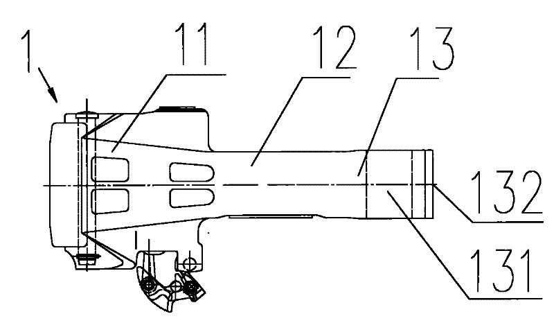
[0053] The basic idea of ​​the present invention is that the tail end surface of the coupler is designed as a cylindrical surface plus a symmetrical shoulder structure, and the slave plate is also designed as a cylindrical surface plus a symmetrical shoulder structure, so as to enhance the automatic centering function of the coupler.

[0054] The following will be described in detail in conjunction with the accompanying drawings and embodiments.

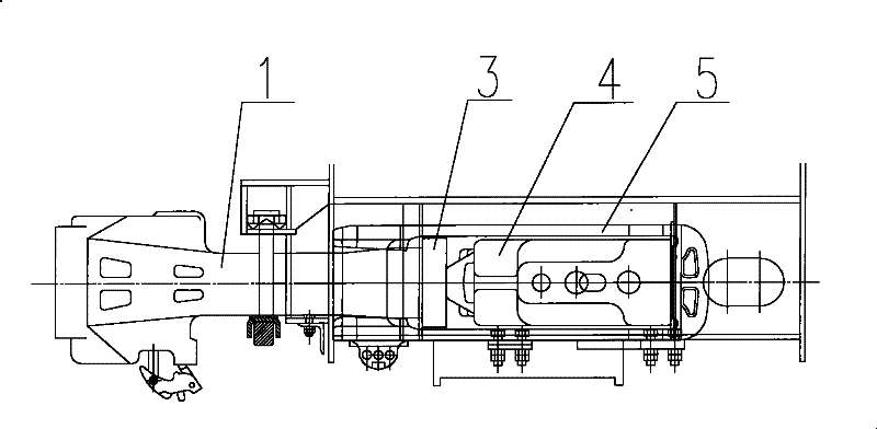
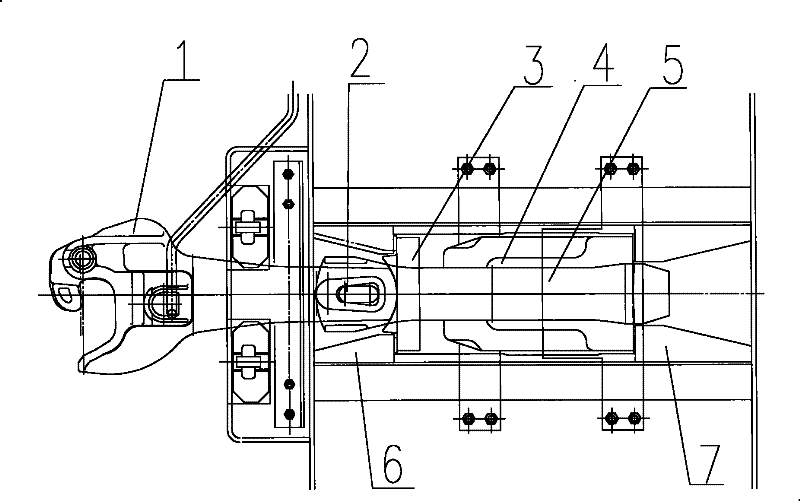
[0055] See Figure 10-11 ,in: Figure 10 It is the structural representation of the coupler of the present invention; Figure 11 yes Figure 10 top view. In the coupler 1, the coupler head 11 includes a knuckle tongue 111, a knuckle tongue pin 115, a knuckle tongue push iron 117, a coupler lock 116, a lower lock pin (including a lower lock pin, a lower lock pin rod 113), and a lower lock pin. Rotating shaft 119; when the lower locking pin rotating shaft 119 rotates, the lower locking pin forms an action to make the hook lock 116 ...


PUM


Abstract

The invention discloses a coupler buffer device including a coupler, a coupler tail frame, a coupler tail pin and slave plates. A coupler head of the coupler comprises a coupler knuckle, a coupler knuckle pin, a coupler knuckle thrower, a coupler lock, a lower lockpin assembly, and a lower lockpin rotating shaft, wherein when the lower lockpin rotating shaft rotates, the lower lockpin assembly actuates to ensure that the coupler lock moves up and down along an inner cavity of the couplerhead of the coupler to drive the rotation of the coupler knuckle thrower to push the coupler knuckle to rotate around the coupler knuckle pin; the middle part of the end surface of a coupler tail of the coupler has a cylindrical surface, and convex shoulders are symmetrically arranged at both sides. A head part width size of the coupler tail frame is near the distance between opposite surfaces of blocks in a base of two front slave plates, so that the distance enables the gap between the coupler tail frame and the blocks in the base of the front slave plates to decrease. Under the drag and compression states, the blocks in the base of the front slave plates can limit the landscape swing of the coupler tail frame so as to lead the coupler buffer device to have guiding and position correction functions.

Description

technical field [0001] The invention relates to a railway vehicle traction device, in particular to a coupler buffer device. Background technique [0002] The coupler buffer device (referred to as the coupler buffer device) is an important part of the railway vehicle. It is located at both ends of the locomotive or vehicle, and is used to realize the mutual connection of the locomotive or vehicle, transmit traction or compression force, and ease the longitudinal impact. The coupler buffer device is mainly composed of coupler, buffer, coupler frame, slave plate, coupler pin and other parts, and is a key component to ensure the safety of railway transportation. [0003] See Figure 1-2 ,in: figure 1 It is a structural schematic diagram of an existing hook buffer device; figure 2 yes figure 1 top view. The coupler buffer device is used in heavy-duty trains SS4G and HXD1 8-axle electric locomotives on the Daqin Line. 2 is connected with the coupler frame 5; when the loco...

Claims


Application Information

Patent Timeline
Patent Type & Authority Patents(China)
IPC IPC(8): B61G1/36B61G7/14B61G7/00B61G9/04
CPCB61G9/24B61G7/12
Inventor 姜岩崔英俊孟庆民陈龙王俊龙王晓龙丛盛国
Owner CRRC QIQIHAR ROLLING CO LTD
Why Eureka
Try Eureka