
Surface shape detection apparatus and method for large-bore plane optical element

A technology for detecting optical components and surface shapes, which is applied in the direction of optical devices, measuring devices, instruments, etc., can solve the problem of high optical system design and structural design requirements of large-aperture Hartmann beam expander systems, and it is difficult to meet transient interference Instrument or LTP requirements, inability to detect the surface shape of optical components, etc., to achieve the effect of easy industrial implementation and application, easy quick adjustment, and convenient industrial promotion

Inactive Publication Date: 2011-06-29
范勇
View PDF0 Cites 0 Cited by
  • Summary
  • Abstract
  • Description
  • Claims
  • Application Information

AI Technical Summary

Problems solved by technology

[0007] The Hartmann detection method is a detection method that samples a wave surface with several small hole apertures. It is less affected by the outside world and has lower requirements for the detection environment than the interferometer. However, the large-aperture Hartmann The optical system design and structural design requirements of the beam expander system are high, and the cost is also high
[0008] The above-mentioned interferometry has high requirements on the detection environment, and the online detection conditions in the ICF laboratory are difficult to meet the requirements of the transient interferometer or LTP, and it is impossible to perform surface shape detection on optical components in different tilt states

Method used


Image

  • Surface shape detection apparatus and method for large-bore plane optical element
  • Surface shape detection apparatus and method for large-bore plane optical element
  • Surface shape detection apparatus and method for large-bore plane optical element

Examples


Embodiment Construction

[0030] The present invention will be further described below in combination with specific embodiments and accompanying drawings.

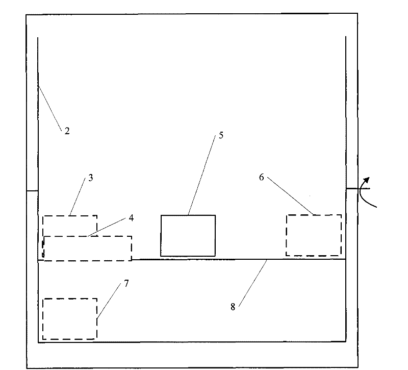
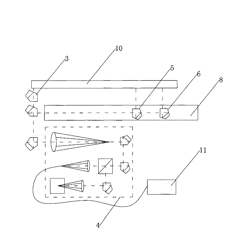
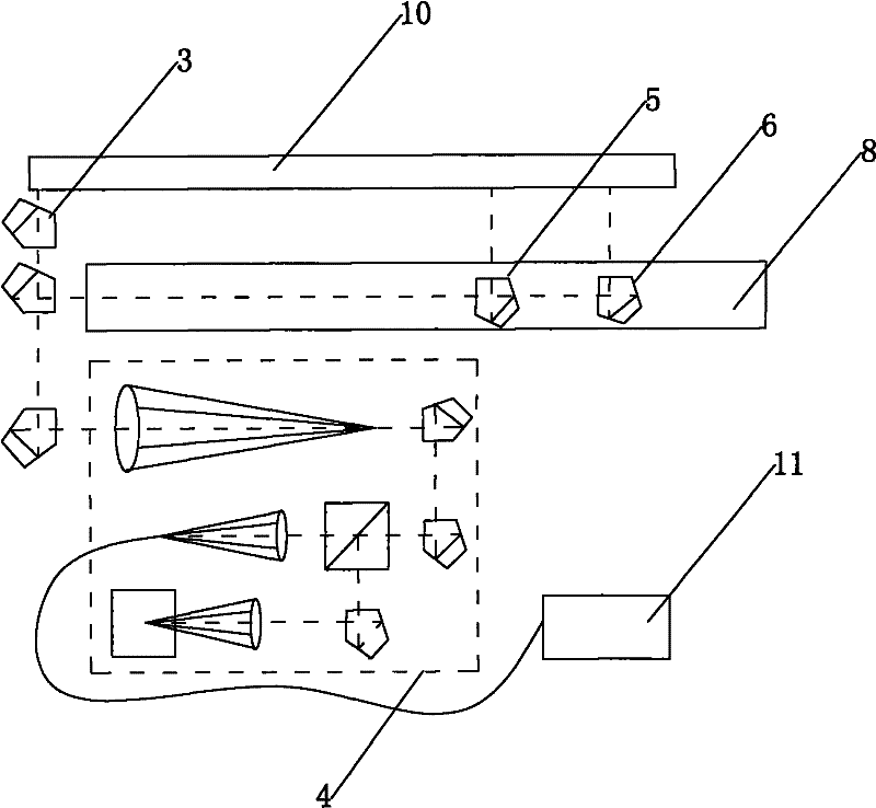
[0031] The surface shape detection device for large-caliber planar optical components includes a frame, an image acquisition and processing system, and a three-dimensional precision motion control system; the three-dimensional precision motion control system includes a vertical motion guide rail that is rotatably installed on the frame, and can Sliding horizontal motion guide rail, the shaft fixedly installed on the vertical motion guide rail is connected with the rotary power mechanism; the image acquisition and processing system includes the first scanning pentaprism arranged on the slider of the horizontal motion guide rail, fixedly installed on the horizontal motion guide rail parallel The first reference pentaprism and the second scanning pentaprism on the axis, the second reference pentaprism fixedly installed on the axis parallel to the verti...


PUM


Abstract

The invention relates to a device and a method for detecting the surface shape of large-caliber plane optical elements, and belongs to a device and a method for detecting the quality of optical elements. The device and the method aim to solve the problems in the prior device and the prior method for detecting the large-caliber plane optical elements. The device comprises a stand, an image acquisition and processing system and a three-dimensional precision motion control system, wherein the three-dimensional precision motion control system comprises a vertical motion guide rail which is rotatably arranged on the stand, and a horizontal motion guide rail which can slide on the vertical motion guide rail; a rotary shaft which is fixed on the vertical motion guide rail is connected with a rotary power mechanism; and the image acquisition and processing system comprises a first scanning penta prism which is arranged on a slider of the horizontal motion guide rail, a first reference penta prism and a second scanning penta prism which are coaxially fixed with the horizontal motion guide rail, a second reference penta prism which is coaxially fixed with the vertical motion guide rail, andan optical head which is coaxially fixed with the horizontal motion guide rail. The device and the method can be applied to detection of the large-caliber plane optical elements, and are particularlysuitable for online detection.

Description

technical field [0001] The invention belongs to an optical element quality inspection device and method, in particular to a surface shape inspection device and method for a large-caliber planar optical element. Background technique [0002] Large-aperture planar optical components are mostly placed horizontally during processing. Due to the influence of gravity, the surface shape will change in a vertical or certain inclination state; at the same time, due to the change of the mechanical support structure, it will also have a greater impact on the surface shape. . Therefore, it is necessary to detect the surface shape of the large-aperture planar optical element in the actual use state. [0003] Surface shape detection mainly includes angle difference method, LTP, transient interferometer and Hartmann detection and other methods. [0004] The principle of the angle difference method is that the change of the surface shape can be reflected by the change of the angle of the ...

Claims


Application Information

Patent Timeline
Patent Type & Authority Patents(China)
IPC IPC(8): G01B11/24
Inventor 范勇陈念年张劲峰杨程
Owner 范勇
Learn More