
Recognition device and method for abnormal heating defect rank of electric power apparatus

A technology for power equipment and defect levels, which is applied to measuring devices, measuring electricity, measuring electrical variables, etc., can solve the problem of inability to directly judge the level of power equipment, and achieve the effect of strong practicability, failure avoidance, and accurate judgment.

Inactive Publication Date: 2009-07-08
SUQIAN POWER SUPPLY COMPANY OF JIANGSU PROVINCE POWER
View PDF0 Cites 25 Cited by
  • Summary
  • Abstract
  • Description
  • Claims
  • Application Information

AI Technical Summary

Problems solved by technology

[0003] At present, infrared temperature measuring instruments are usually used to detect abnormal heating of power equipment in substations, but when the infrared temperature measuring instrument measures a high temperature in a certain part of the power equipment, it is impossible to directly judge the level of defects in the power equipment

Method used


Image

  • Recognition device and method for abnormal heating defect rank of electric power apparatus
  • Recognition device and method for abnormal heating defect rank of electric power apparatus
  • Recognition device and method for abnormal heating defect rank of electric power apparatus

Examples


Embodiment 1

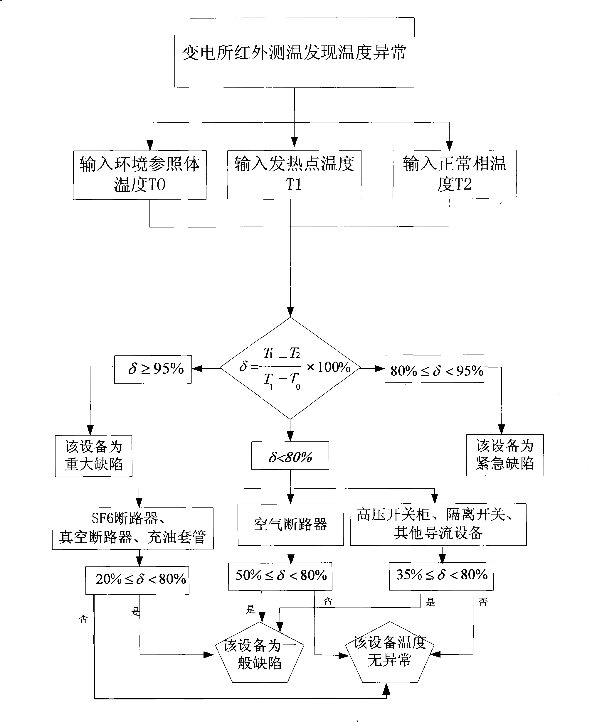
[0024] The temperature of a certain phase of oil-filled bushing equipment in a substation was measured by infrared thermometer as T1 = 100 °C, the temperature of the normal phase was T2 = 30 °C, and the temperature of the environmental reference body at that time was T0 = 25 °C. The infrared thermometer transmits the three measured temperature values ​​to the temperature difference calculator, and the temperature difference calculator is based on the formula δ = T 1 - T 2 T 1 - T 0 × 100 % The relative temperature difference δ=93.3% is obtained, and the temperature difference calculator sends the value of the relative temperature difference δ to the PC. The PC judges that 80%≤δ<95%, and the PC displays the information as "major defect...

Embodiment 2

[0026] The temperature of a certain phase of the air circuit breaker equipment in a substation is measured by infrared thermometer as T1=120°C, the temperature of the normal phase is T2=30°C, and the temperature of the environmental reference body at that time is T0=28°C. The infrared thermometer transmits the three measured temperature values ​​to the temperature difference calculator, and the temperature difference calculator is based on the formula δ = T 1 - T 2 T 1 - T 0 × 100 % The relative temperature difference δ=97.8% is obtained, the temperature difference calculator sends the value of the relative temperature difference δ to the PC, and the PC judges that δ≥95%, and the PC displays the information as "emergency defect" throu...

Embodiment 3

[0028] The temperature of a certain phase of the SF6 circuit breaker equipment in a substation was measured by infrared thermometer as T1=90°C, the temperature of the normal phase was T2=40°C, and the temperature of the environmental reference body at that time was T0=25°C. The infrared thermometer transmits the three measured temperature values ​​to the temperature difference calculator, and the temperature difference calculator is based on the formula δ = T 1 - T 2 T 1 - T 0 × 100 % The relative temperature difference δ=76.9% is obtained, the temperature difference calculator sends the value of the relative temperature difference δ to the PC, and the PC judges that δ<80%, and then performs the secondary identification operation, the...


PUM


Abstract

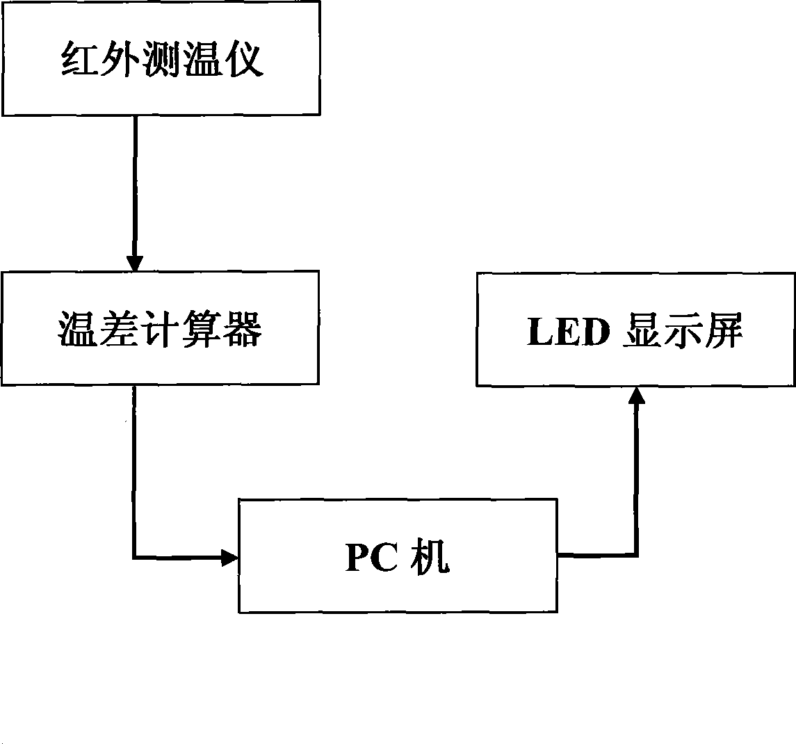
The invention discloses an identification device and an identification method for abnormal heating defect class of power equipment. The identification device is formed by orderly connecting an infrared thermometer, a temperature difference calculator, a PC, and an LED display screen in series, wherein the infrared thermometer is used for measuring temperature, the temperature difference calculator is used for calculating a value of relative temperature difference, the PC is used for calculating and identifying the defect class of abnormal heating equipment, and the LED display screen is used for outputting a result of the identification. The identification method utilizes the infrared thermometer to measure three temperature values, namely the heating point temperature T1 of the power equipment, the temperature T2 of a non-fault phase and the temperature T0 of an environmental reference body, calculates the relative temperature difference delta through the temperature difference calculator, then utilizes the PC to identify different defect classes according to different power equipment, and displays the result of the identification through the LED display screen. The identification device and the identification method can reliably and conveniently judge the defect property of the heating equipment, arrange the overhaul in time, and avoid the further enlargement of fault.

Description

technical field [0001] The invention relates to an identification device and an identification method for abnormal heating defect levels of electric equipment, belonging to the field of electric equipment detection. Background technique [0002] Power equipment usually works in high voltage and high current state, and some equipment defects can lead to abnormal temperature rise of equipment components. For example, there are a large number of conductor crimp connections and plug connections in power equipment. If the crimp or plug connections are not tight, the contact resistance will increase, and the temperature will rise abnormally under the action of high current. The increase in temperature further increases the contact resistance, resulting in a vicious circle, which may eventually cause the device to malfunction or even burn out. Real-time detection of the temperature of power equipment and timely defect analysis of the detected temperature are of great significance ...

Claims


Application Information

Patent Timeline
Patent Type & Authority Applications(China)
IPC IPC(8): G01R31/00G01R31/327G01J5/00
Inventor 李江成
Owner SUQIAN POWER SUPPLY COMPANY OF JIANGSU PROVINCE POWER
Learn More