
Wire harness test control panel and wire harness test control method

A technology for testing control and wiring harness, which is applied in the field of wiring harness test control board, and can solve the problems of many branches and relays in the wiring harness

Active Publication Date: 2009-07-08
深圳市大为创新科技股份有限公司
View PDF1 Cites 29 Cited by
  • Summary
  • Abstract
  • Description
  • Claims
  • Application Information

AI Technical Summary

Problems solved by technology

[0007] The purpose of the present invention is to overcome the shortcomings of the above-mentioned prior art, provide a test signal that can output 24V and ground, and can detect three states of 24V, ground, and suspension; effectively detect whether the relay on the wiring harness is working normally , Whether the diode is short-circuited or open-circuited; the test program can be written according to the corresponding single-chip microcomputer according to the different functional wiring harness design, and the test result can be displayed through the display and the unqualified alarm circuit, and the test result can also be uploaded to the PC through the serial port for statistics and analysis. Use the wiring harness test control board with many wiring harness branches, relays, diodes and other complex wiring harness detection problems

Method used


Image

  • Wire harness test control panel and wire harness test control method
  • Wire harness test control panel and wire harness test control method
  • Wire harness test control panel and wire harness test control method

Examples


Embodiment Construction

[0040] The present invention will be described in further detail below in conjunction with accompanying drawing:

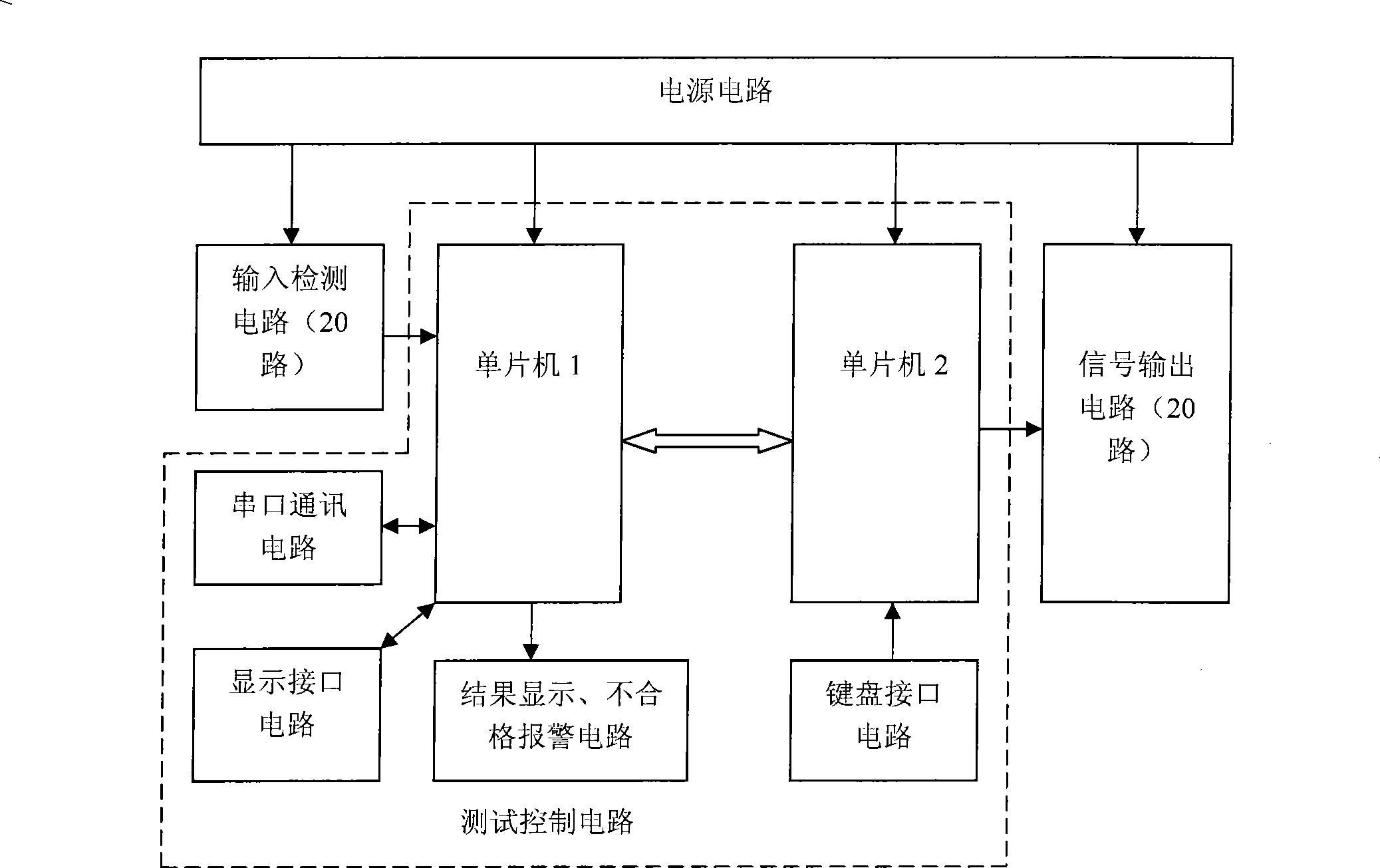
[0041] see figure 1 As shown, the harness test control board described in this embodiment includes:

[0042] A power supply circuit, respectively connected to the signal input detection circuit, test control circuit, and signal output circuit to provide power for them;

[0043] A signal input detection circuit, the output end of which is connected to the input end of the test control circuit, and is used to detect three signal states of 24V, grounded and floating;

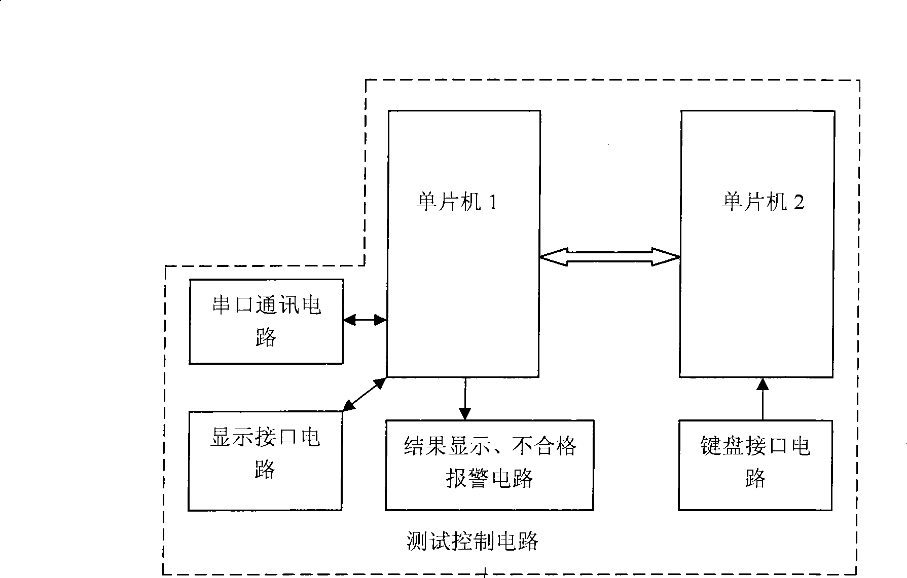
[0044] A test control circuit, the output end of which is connected to the input end of the signal output circuit for output control, input detection, display signal output, key input, alarm, and communication;

[0045] A signal output circuit is used to output 24V or ground signal.

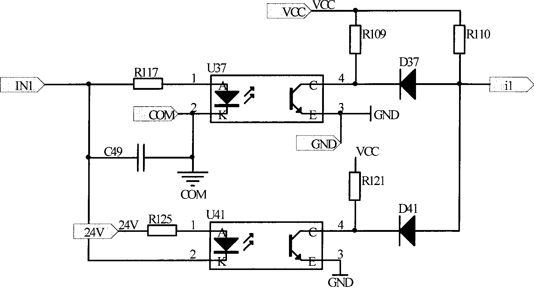
[0046] see figure 2 As shown, the signal input detection circuit described in this embodiment consists of a photoc...


PUM


Abstract

The invention relates to a wiring harness test control board and a wiring harness test control method. The method comprises the following steps: singlechips are initialized; a singlechip (1) detects whether a keypress signal exists; the input keypress signal is transmitted to a singlechip (2), and the singlechip (2) displays pressed keys; whether a pound key is pressed is judged, and the keypress signal saved in the singlechips is cleared to wait for the re-entry; the singlechip (2) judges whether a pound key is pressed; a six-digital number which is input through a keyboard is saved; test procedures with corresponding codes are executed, the singlechip (1) outputs a test signal, and the singlechip (2) detects an input signal; the judgment is made by comparing with the standard; a test result is displayed on a liquid crystal; the alarm is performed if the test result is unqualified; and a serial port communication program is transferred to a host computer. The wiring harness test control board and the wiring harness test control method solve detection problems of complex wiring harnesses, for example, wiring harnesses for automobiles have more branches, relays and diodes are arranged on the wiring harnesses, and can detect three states, namely 24V, grounding and suspension, and whether the relays on the wiring harnesses work normally and the diodes are short-circuited and open-circuited.

Description

technical field [0001] The invention relates to a wire harness test control board, in particular to a wire harness test control board for automobiles with many branches and complex wire harness detection such as relays and diodes on the wire harness. Background technique [0002] CN200710104367.8 discloses "a wire harness tester". Its purpose is to provide a bidirectional test for wire harnesses, which can detect diodes, bulbs, resistors, and capacitors connected in cables, and can detect more complex wire harness connections without programming. Standard wire harnesses can directly generate standard data, and Wire harness tester with simple structure. Its disadvantages are: [0003] 1. The output circuit cannot output 24V, and cannot drive the car relay, so the car wiring harness with relay cannot be detected. [0004] 2. The input detection circuit cannot distinguish low level and floating signals. [0005] 3. The test results cannot be transmitted to the upper compute...

Claims


Application Information

Patent Timeline
IPC IPC(8): G01R31/00G01R31/327G01R31/02G01R1/28
Inventor 凌兆蔚黄斌闻维维向守胜梁勇
Owner 深圳市大为创新科技股份有限公司
Learn More