Array antenna and electronic device using same

A technology for array antennas and electronic devices, which is applied to the combination of antenna elements with different polarization directions, etc., and can solve the problems affecting the signal reception effect and loss at the receiving end

Active Publication Date: 2009-07-08
ASUSTEK COMPUTER INC
View PDF0 Cites 16 Cited by
  • Summary
  • Abstract
  • Description
  • Claims
  • Application Information

AI Technical Summary

Problems solved by technology

When the signal is transmitted from the base station, the polarization direction of the signal will be changed or rotated due to obstacles, thus affecting the signal reception effect at the receiving end
[0004] If the base station is dual-polarized and the antenna of the electronic device is single-polarized, then the signal transmitted by the electronic device will also cause polarization loss when it is transmitted to the base station

Method used


Image

  • Array antenna and electronic device using same
  • Array antenna and electronic device using same
  • Array antenna and electronic device using same

Examples


no. 1 example

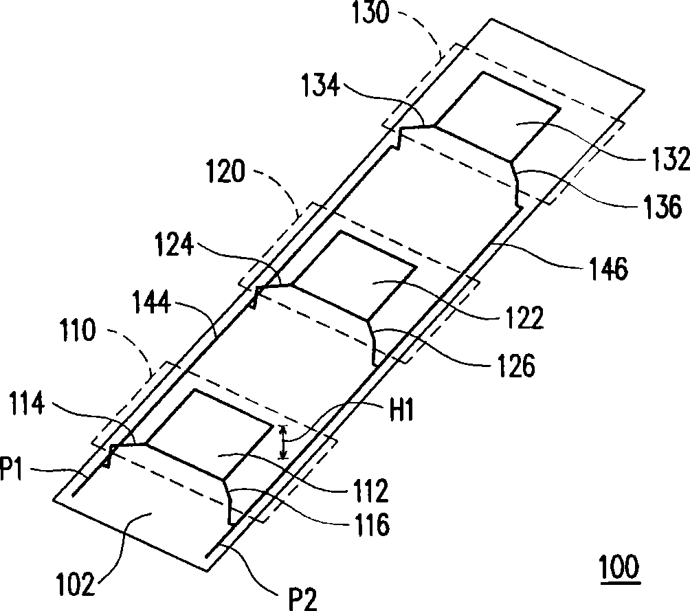
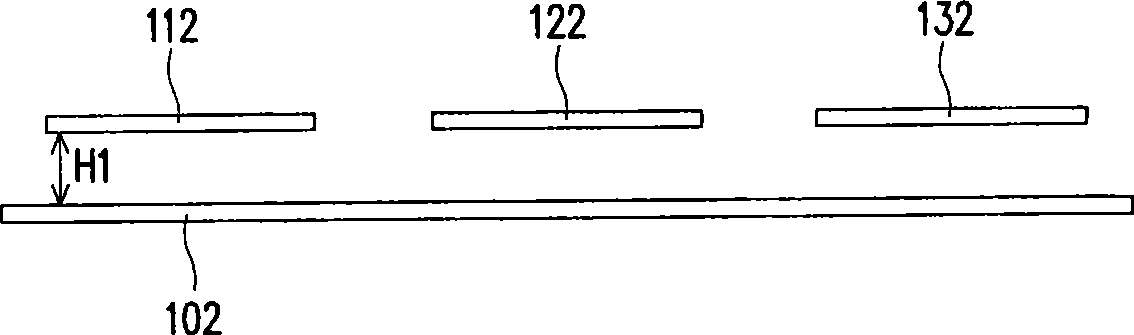
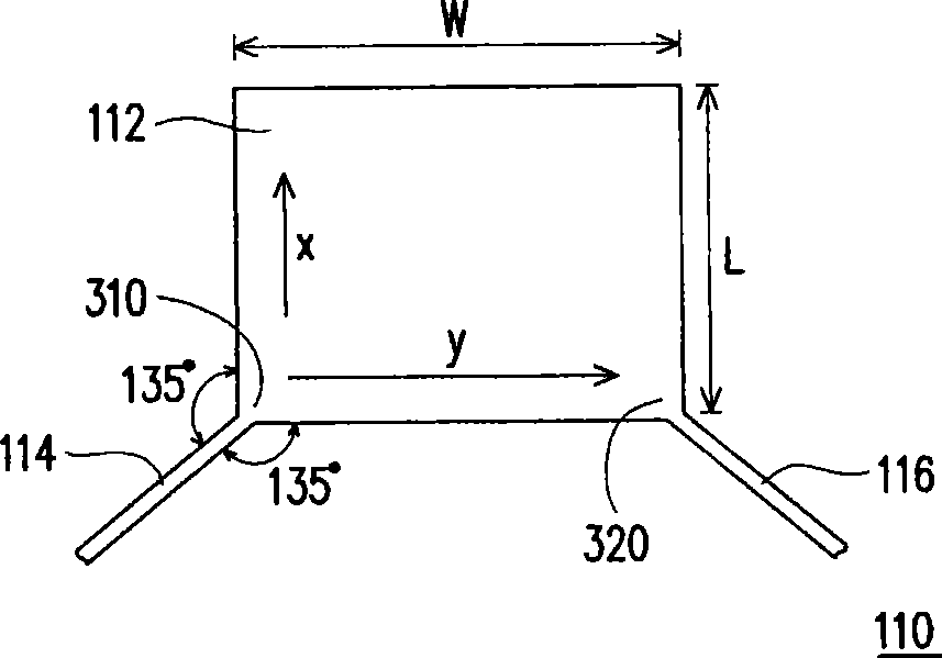
[0069] figure 1 is the array antenna according to the first embodiment of the present invention. The array antenna 100 includes a substrate 102 , antenna units 110 - 130 and connecting wires 144 , 146 . The antenna unit 110 includes a rectangular radiation area 112 and feeders 114 and 116 , wherein the rectangular radiation area 112 can be a rectangle or a square, respectively having four sides and four feeding angles. One ends of the feed lines 114 and 116 are respectively connected to two adjacent feed angles of the rectangular radiation area 112 , and the structures of the antenna units 120 - 130 are the same as the antenna unit 110 . In this embodiment, the antenna units 120-130 are arranged in a straight line and are equidistant from each other, and the connection lines 144, 146 are respectively arranged on the two sides of the rectangular radiation areas 112, 122, 132, and the connection line 144 is used to connect The other end of the feeder lines 114 , 124 , 134 of t...

no. 2 example

[0081] In order to increase the gain of the array antenna 100 and adjust the radiation pattern of the array antenna 100, in this embodiment, a coupler can be provided above the antenna units 110-130, such as Figure 4A as shown, Figure 4A is an array antenna according to the second embodiment of the present invention. Figure 4A The array antenna 400 in the aforementioned image 3 The main difference of the array antenna 300 is that the couplers 450, 460, 470 are arranged above the rectangular radiation areas 412, 422, 432, respectively. The second difference is that the rectangular radiating regions 412, 422, 432 in this embodiment are directly formed on the upper surface of the substrate 402, while the reflector (not shown) is formed at the positions corresponding to the rectangular radiating regions 412, 422, 432. the lower surface of the substrate 402 .

[0082] The design of the rectangular radiation areas 412 , 422 , 432 and the connection relationship between them a...

no. 3 example

[0086] Please refer to Figure 5A , Figure 5A is an array antenna according to the third embodiment of the present invention. Array antenna 500 includes antenna unit 510, 520, 530, feeder 514, 515, 516, 517 and rectangular radiation area 512 form antenna unit 510; feeder 524, 525, 526, 527 and rectangular radiation area 522 form antenna unit 520; and feeder 534 , 535 , 536 , 537 and the rectangular radiation area 532 form an antenna unit 530 again. The connection line 544 is connected to the other end of the feeder 514, 524, 534; the connection line 546 is connected to the other end of the feeder 516, 526, 536; the connection line 545 is connected to the other end of the feeder 515, 525, 535; the connection line 547 is connected to The other end of the feeder lines 517, 527, 537. In other words, the four feeding corners of the rectangular radiation areas 512, 522, 532 are respectively connected to the four connection lines 544, 546, 545, 547, and the four connection ports of...


PUM


Abstract

The invention provides an array antenna and an electronic device using the array antenna. The array antenna comprises a plurality of antenna elements, a first connecting wire and a second connecting wire. Each antenna element comprises a rectangular radiation zone, a first feeder and a second feeder. The first feeder and the second feeder are connected with the two adjacent feed-in angles of the rectangular radiation zone; and the first connecting wire and the second connecting wire are arranged on the two sides of the antenna element respectively, and connected with the other ends of the first feeder and the second feeder.

Description

technical field [0001] The present invention relates to an array antenna, and in particular to an array antenna capable of receiving dual-polarized or circular-polarized signals and an electronic device using the array antenna. Background technique [0002] With the continuous evolution and improvement of electronic technology and manufacturing technology, humanized and functional information products are constantly being introduced. Because the pace of life is accelerating today, and communication methods are more time-sensitive, mobile phones have replaced traditional phones. With their portability and convenience, they are regarded as the most convenient and fastest communication tools between people. In addition, with the rapid development of wireless communication technology, electronics with wireless Internet access functions are becoming more and more popular, such as notebook computers (notebooks), personal digital assistants (personal digital assistants, PDAs), and ...

Claims


Application Information

Patent Timeline
Patent Type & Authority Applications(China)
IPC IPC(8): H01Q21/24
Inventor 刘明彦邓天隆蔡孝明陈世杰黄子卿
Owner ASUSTEK COMPUTER INC
Why Eureka
Try Eureka