
Method and system for RRPP loop link switching

A ring chain and loop detection technology, which is applied in the field of network communication, can solve the problems of unaware links and RRPP ring traffic interruption, etc., and achieve the effect of fast link switching and reducing traffic interruption time

Inactive Publication Date: 2009-07-08
NEW H3C TECH CO LTD
View PDF0 Cites 15 Cited by
  • Summary
  • Abstract
  • Description
  • Claims
  • Application Information

AI Technical Summary

Problems solved by technology

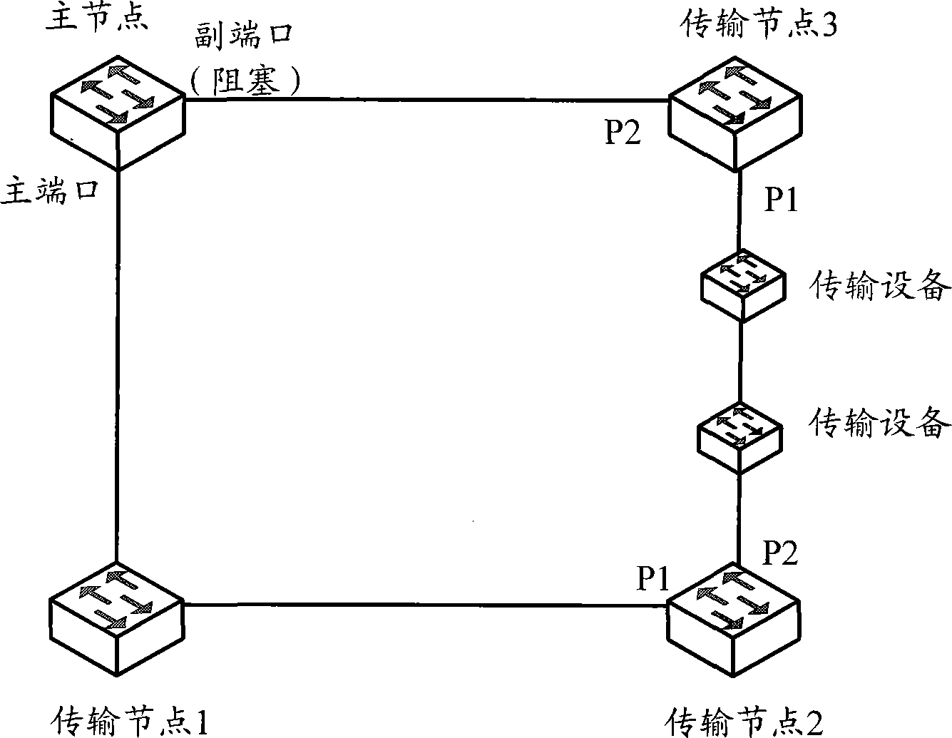
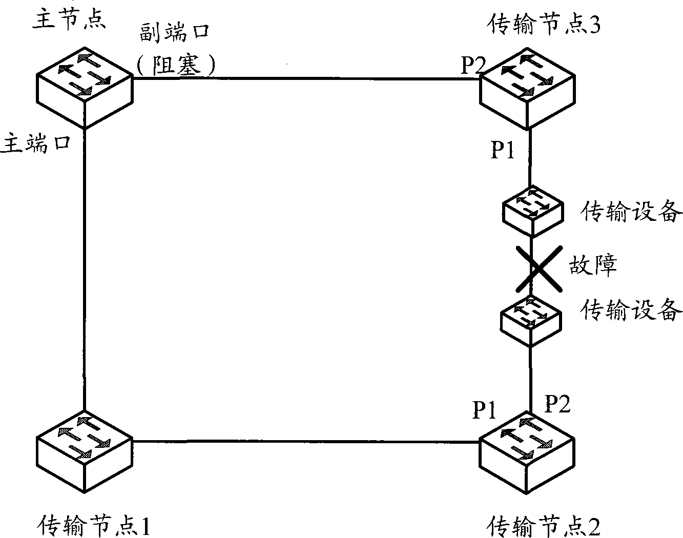
[0004] The method of performing RRPP ring link switching in the prior art is usually: if the transit node senses that the link it is connected to fails, it sends a link failure (Link_down) message to the master node, and the master node receives the Link_down message Finally, switch the secondary port of the primary node to the forwarding state on the data VLAN, and send the Common_Flush_FDB message through the primary port and the secondary port. However, this method is only applicable to the link where the link failure occurs on the link directly connected to the transit node. if happens as figure 2 In the situation shown, that is, the link failure occurs between the transmission devices instead of the link directly connected to the transmission node, the transmission node cannot perceive the link failure, and can only get the secondary port after the Fail timer expires. , RRPP ring failover
Since the sending interval of the loop detection message is usually 2s, the timing duration of the Fail timer is set to be greater than the sending time interval of three loop detection messages, which is usually 7s. Therefore, it is necessary to wait for 7s after a fault occurs The link switching of the RRPP ring can only be performed after a long time, which will inevitably cause a long-term interruption of traffic in the RRPP ring

Method used


Image

  • Method and system for RRPP loop link switching
  • Method and system for RRPP loop link switching
  • Method and system for RRPP loop link switching

Examples


Embodiment Construction

[0018] In order to make the object, technical solution and advantages of the present invention clearer, the present invention will be described in detail below in conjunction with the accompanying drawings and specific embodiments.

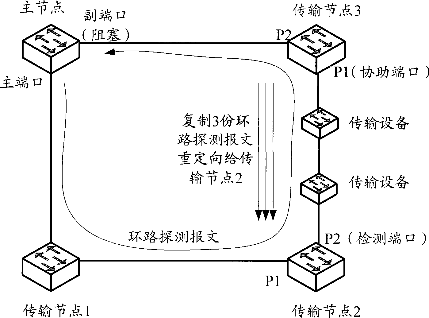
[0019] The method provided by the present invention mainly includes: enabling the fault detection feature on the transmission node port directly connected to the transmission equipment link on the RRPP ring, and first receiving the loop detection message in the port with the fault detection feature enabled The port is used as a detection port, and the other port is used as an assisting port; after the transmission node where the assisting port is located receives a loop detection message through the assisting port, it forwards the loop detection message and copies N loop detection messages through the assisting port Redirect to the detection port; if the transmission node where the detection port is located does not receive the loop detection messa...


PUM


Abstract

The invention provides a rapid ring protection protocol (RRPP) ring link switching method and a system thereof. Transmission node ports which directly link a RRPP ring and a transmission equipment link are enabled with a fault detection feature, one port of the ports enabled with the fault detection feature, which firstly receives a ring circuit detection message sent from a master node, is used as a detection port, and the other port is used as an assistant port. The method comprises that the transmission node where the assistant port locates forwards a ring circuit detection message after receiving the ring circuit detection message via the assistant port, and copies N ring circuit detection messages and redirects to the detection port via the assistant port, wherein, N is an integer larger than 1; and the transmission node where detection port locates notifies the link fault to the master node if not receiving the ring circuit detection message via the detection port within a set time period after sending the ring circuit detection message via the detection port. The method and the system can reduce traffic interrupting time in the RRPP ring when a fault occurs in the transmission equipment link.

Description

technical field [0001] The present invention relates to network communication technology, in particular to a method and system for rapid ring protection protocol (RRPP, RapidRing Protection) ring link switching. Background technique [0002] RRPP is a link layer protocol specially used for Ethernet rings. When the Ethernet ring is complete, it can prevent broadcast storms caused by data loops. When any link on the Ethernet ring is disconnected, it can quickly restore the communication between nodes on the ring network. Communication link, generally, an RRPP-enabled Ethernet ring is called an RRPP ring. [0003] Generally, an RRPP ring includes three network devices: master node, transit node, and transit device, such as figure 1 As shown in the figure, the master node and the transit node are RRPP-enabled network devices and have ports connected to the RRPP ring. The transit device is usually only used for the connection between transit nodes to forward data packets and con...

Claims


Application Information

Patent Timeline
IPC IPC(8): H04L12/437H04L12/56H04L29/08H04L12/937
Inventor 顾雷雷王军周迪
Owner NEW H3C TECH CO LTD
Learn More