Modular hip implant

An implant and modular technology, applied in the direction of joint implants, joint implants, hip joints, etc., can solve problems such as unfavorable anteversion, and achieve the effects of avoiding dislocation, improving stability, and avoiding contact

Inactive Publication Date: 2009-07-08
彼得布雷姆控股两合公司
View PDF1 Cites 9 Cited by
  • Summary
  • Abstract
  • Description
  • Claims
  • Application Information

AI Technical Summary

Problems solved by technology

Furthermore, it can happen that the individual parts of the bearing ring rotate relative to each other after surgery due to stronger mechanical loads, so

Method used


Image

  • Modular hip implant
  • Modular hip implant
  • Modular hip implant

Examples


Embodiment Construction

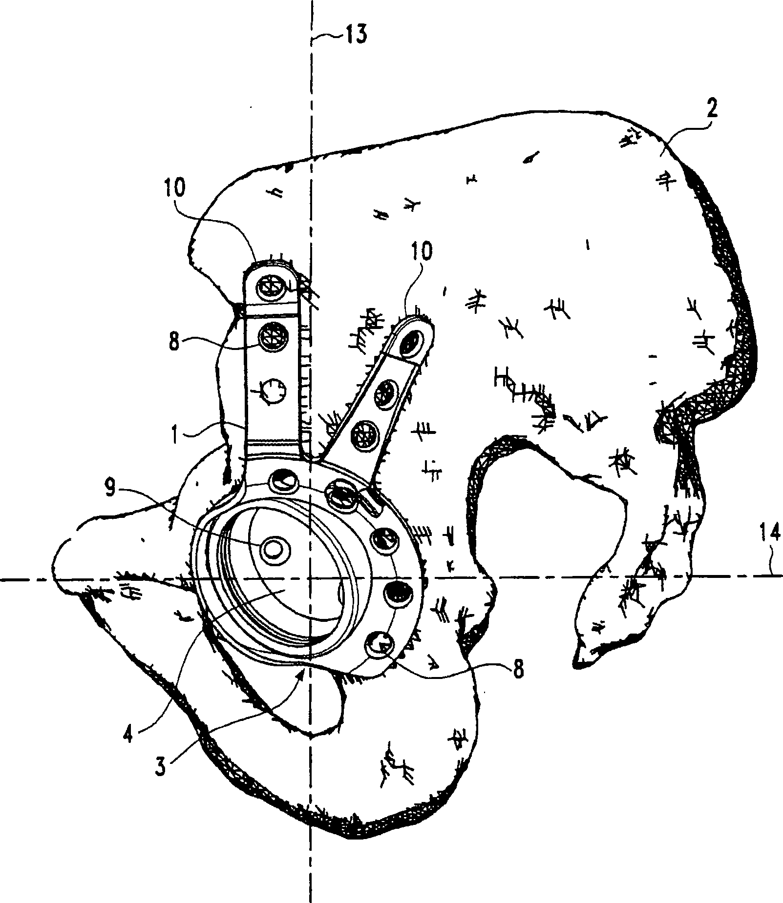
[0085] figure 1 A modular hip implant according to the invention is shown with a base body 1 fixed on a hip bone 2 . The base body 1 has a bowl-shaped receiving area 3 . A glenoid socket 4 is inserted into the receiving area 3 .

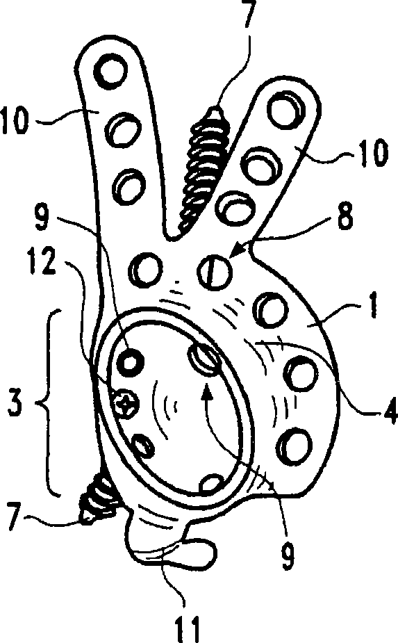
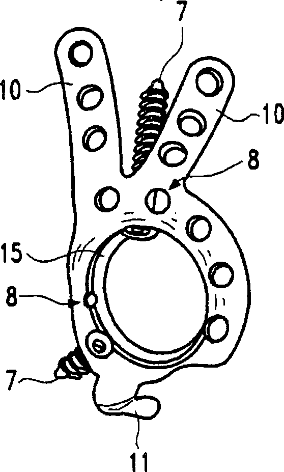
[0086] The basic body 1 has fastening means for fastening it to the hip bone. Bolts, such as dome bolts 7, can be used as fastening means. Fixtures (particularly dome bolts 7) at figure 1 not shown in. However, the dome bolt 7 is in figure 2 and image 3 in the icon. Holes 8 are machined in the base body 1 . Additional holes 9 are also machined in the glenoid socket 4 .

[0087] The base body 1 has two straps 10 and a tongue 11 . they are figure 1 not visible in , but in figure 2 and image 3 in the icon. The straps 10 are arranged adjacent to one another. They are located on the side opposite the tongue 11 . The straps 10 are likewise provided with holes 8 and the receiving area 3 is also provided with holes 8 . For example, the ...


PUM


Abstract

The invention relates to a modular hip implant comprising a base that is to be attached to a hipbone, and a socket for accommodating a hip joint prosthesis. The base is provided with fastening means for mounting the base on the hipbone as well as a concave receiving area for the socket. The socket has a convex outer form which is complementary to the receiving area such that the radii of curvature determining the concave receiving area and the convex outer form essentially correspond to each other. The socket can be fastened within the base. The inventive hip implant is characterized in that the base and/or the socket encompass/es means for adjusting the position of the socket relative to the base. The invention allows the inclination and anteversion to be adjusted by arranging the socketinside the base.

Description

technical field [0001] The present invention relates generally to hip implants, and more particularly to a modular hip implant with a suction cup-like support bowl for fixation on the hip bone. A base body and a socket for receiving a hip joint prosthesis, wherein the base body is fixable on the hip bone and has a receiving area for the socket, and the socket has an outer shape complementary to the receiving area. Background technique [0002] The artificial hip joint has a hip prosthesis to be loaded into the femur and a hip socket to be installed on the hip bone. The end of the hip prosthesis facing away from the knee is spherically configured to engage in the hip socket of the hip implant and form a ball joint therewith. [0003] If the pelvis no longer provides sufficient bony mass to reliably anchor the simple hip socket, additional support in a ring or bowl configuration is required. The additional support is preferably used in hip replacement surgery, where actual b...

Claims


Application Information

Patent Timeline
IPC IPC(8): A61F2/34
CPCA61F2/30744A61F2250/0058A61F2002/30535A61F2/34
Inventor 彼得·布雷姆
Owner 彼得布雷姆控股两合公司
Why Eureka
Try Eureka