
Lock nut

A technology for locking nuts and nuts, which is applied in the direction of nuts, locking fasteners, screws, etc., and can solve problems such as inability to achieve precision and appearance of bolts

Inactive Publication Date: 2009-07-08
J 伦登
View PDF1 Cites 3 Cited by
  • Summary
  • Abstract
  • Description
  • Claims
  • Application Information

AI Technical Summary

Problems solved by technology

However, if the nut is adjusted with high accuracy requirements, this adjustment method cannot achieve sufficient accuracy.
Another disadvantage is that holes appear in the bolts

Method used


Image

  • Lock nut
  • Lock nut
  • Lock nut

Examples


Embodiment Construction

[0013] In short, the lock nut of the present invention is longer than normal nuts. At one end thereof, it is substantially radially open in several directions, while in the opening a locking claw is placed which under certain conditions bites into the surface / thread of the bolt onto which the nut is screwed. However, in other cases it will not bite into the surface.

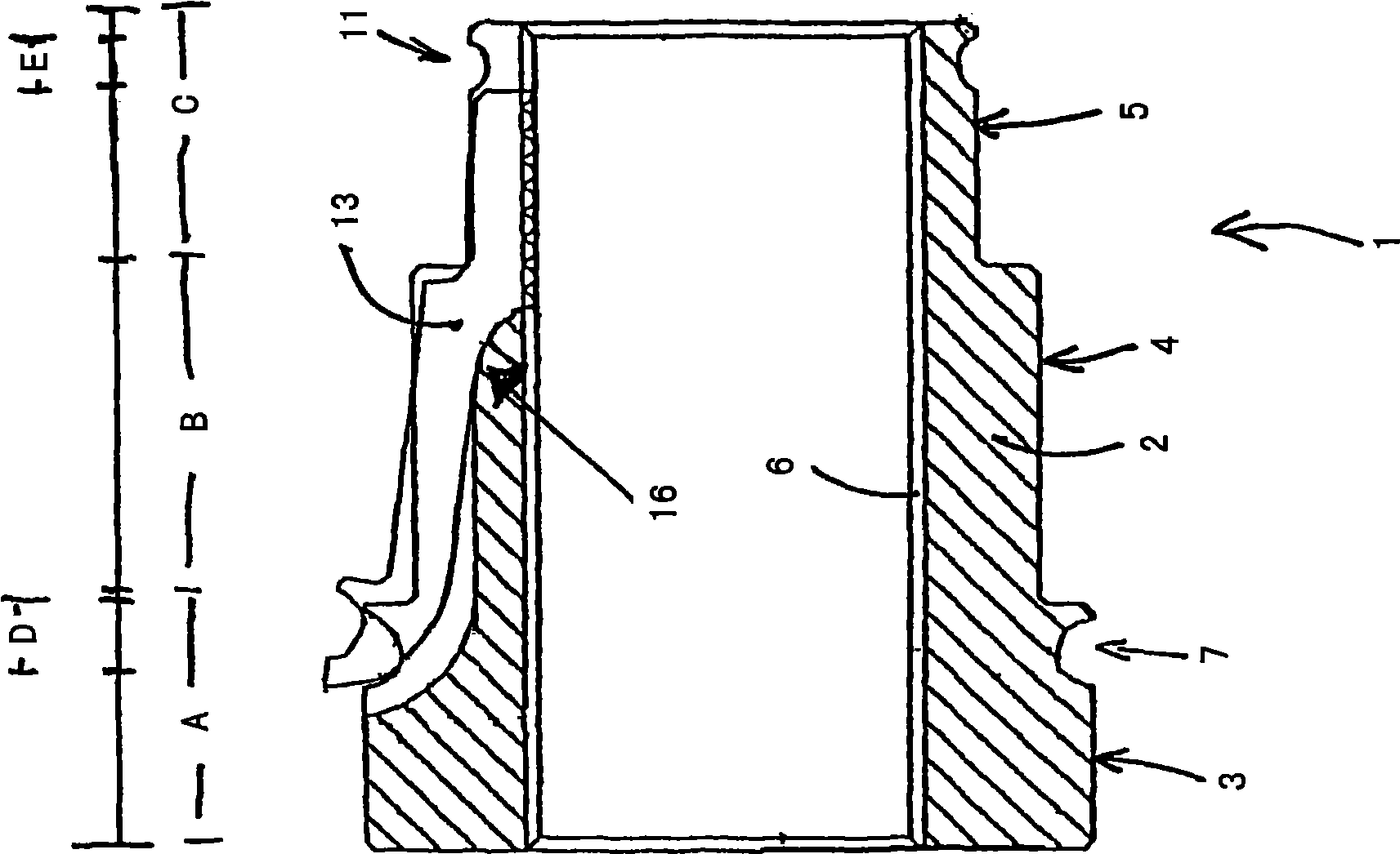
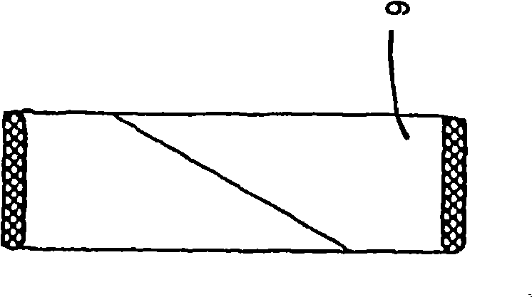
[0014] Combine below figure 1 with Image 6 It is described in detail because some features only appear in one or the other of these two figures.

[0015] figure 1 Shows the sectional plane of locknut 1 among the present invention, for clarity, has been figure 2 , 3, and parts shown in 4 removed. The nut is formed by the body part 2, in figure 1 The part shown as hatching in . Conventionally, the bore runs through the nut and has a standard internal thread 6 in the bore.

[0016] Usually, the body is formed of three separate parts in the longitudinal direction, wherein the most extended part 3 can be of ...


PUM


Abstract

Lock nut, comprising a nut body (2), in which there is a drill hole equipped with an internal thread for a bolt body equipped with an external thread. In the nut there are essentially axial cuts (12), which extend to the drill hole over part of its length, and locking claws (13) in the said cuts, to bite when pressed against the bolt, to prevent the nut from opening.

Description

technical field [0001] The invention relates to a lock nut. In particular, it relates to a lock nut suitable for demanding applications. Background technique [0002] Under conditions of vibration, movement or other high requirements, with detachable joints, the locking is usually achieved by locking the nut, which locks the accessory in its position so that the nut cannot be screwed due to vibration or other reasons. cause the connector to loosen. [0003] One solution to achieve the above object is to change part of the threads of the nut to be made of slightly compressible plastic, usually nylon. Such a nut can be used in many occasions, but it is still not suitable for some demanding situations. The purpose of using the above solution is that when the nut is screwed in place, once the thread on the nut reaches the nylon part, the tightening force must be increased. To some extent, this solution has reached a certain level, but it still cannot be used in demanding con...

Claims


Application Information

Patent Timeline
IPC IPC(8): F16B39/32
CPCF16B39/32F16B39/00
Inventor J·伦登
Owner J 伦登
Learn More