A flexible tower

A tower and flexible technology, applied in the direction of small buildings, industrial buildings, etc., can solve problems such as limitations in the scope of application, and achieve the effects of enhanced buoyancy, small expansion coefficient, and high tensile strength

Inactive Publication Date: 2017-03-22
NO 63655 TROOPS OF THE CHINESE PEOPLES LIBERATION ARMY
View PDF3 Cites 0 Cited by
  • Summary
  • Abstract
  • Description
  • Claims
  • Application Information

AI Technical Summary

Problems solved by technology

Therefore, there are the above defects in the existing towers, and the scope of application also has certain limitations

Method used


Image

  • A flexible tower
  • A flexible tower
  • A flexible tower

Examples


Embodiment 1

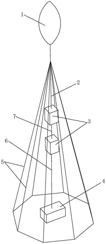
[0035] Such as figure 1 The shown flexible tower includes a main buoyancy airbag 1, a carrying airbag 3 and a counterweight 4, the main buoyancy airbag 1 is arranged above the carrying airbag 3, and the counterweight 4 is arranged under the carrying airbag 3, The main buoyancy airbag 1 is connected with the carrying airbag 3 through the first plumb rope 2, and the carrying airbag 3 is connected with the counterweight 4 through the second plumb rope 6, and a week of the carrying airbag 3 is provided with a plurality of A stay rope 5, the upper end of the stay rope 5 is connected to the first plumb rope 2, and the lower end of the stay rope 5 is connected to the ground.

[0036] In this embodiment, the total buoyancy of the flexible tower is equal to the sum of the buoyancy provided by the main buoyancy airbag 1 and the buoyancy provided by the carrying airbag 3, wherein the main buoyancy airbag 1 is the main provider of buoyancy, and the main buoyancy airbag 1 is the main provi...

Embodiment 2

[0049] Such as Figure 4 As shown, the difference between this embodiment and Embodiment 1 is that: at least one auxiliary buoyancy airbag 8 is connected in series on the first plumb rope 2 , and the upper end of the oblique stay rope 5 is connected to the first plumb rope 2 The connection point of is positioned at the below of auxiliary buoyancy air bag 8.

[0050] In this embodiment, by setting the auxiliary buoyancy airbag 8, the buoyancy can be enhanced. At this time, the total buoyancy of the flexible tower is equal to the buoyancy provided by the main buoyancy airbag 1, the buoyancy provided by the carrying airbag 3 and the buoyancy provided by the auxiliary buoyancy airbag 8. Sum. At the same time, the auxiliary buoyancy airbag 8 can also effectively limit the swing range of the main buoyancy airbag 1 , and can also ensure that the first plumb line 2 remains in a vertical position.

[0051] Such as Figure 4 As shown, the connection point M between the upper end of t...

Embodiment 3

[0054] Such as Figure 5 As shown, the difference between this embodiment and Embodiment 2 is that: the carrying airbag 3 is a triangular airbag. At this time, the outer surface of the bearing airbag 3 is an inclined plane, when the bearing airbag 3 is as Figure 5 In the arrangement shown, the inclination angle of its outer surface can effectively weaken the gravity on the instrument on it, so that the instrument can be firmly connected to the carrying airbag 3 .

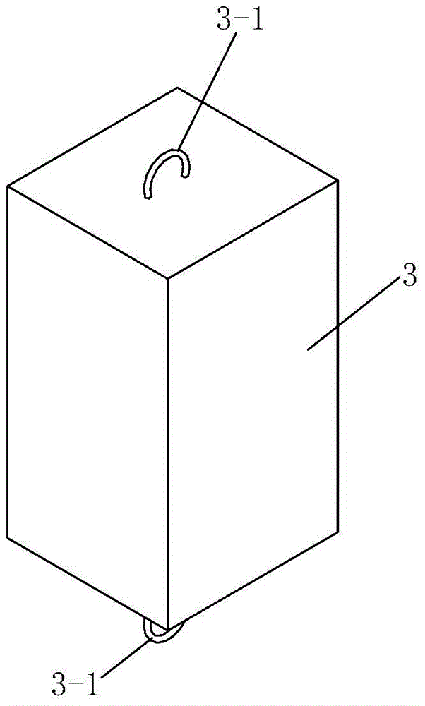
[0055] Such as Figure 6 As shown, the upper end and the lower end of the bearing airbag 3 are all provided with a suspension ring 3-2 for connecting with a plumb line


PUM


Abstract

The invention discloses a flexible tower, which comprises a main buoyant air bag, a bearing air bag and a counterweight, wherein the main buoyant air bag is arranged above the bearing air bag, and the counterweight is arranged under the bearing air bag; the main buoyant air bag is connected with the bearing air bag through a first vertical rope, and the bearing air bag is connected with the counterweight through a second vertical rope; a plurality of inclined pulling ropes are arranged on the rim of the bearing air bag, the upper ends of the inclined pulling ropes are connected with the first vertical rope, and the lower ends of the inclined pulling ropes are connected with the ground. The flexible tower has high stability and quick and easy operation, so that the flexible tower can be quickly stood in the wild; a platform is effectively provided for bearing light measuring equipment or navigation channel and height markers, and the flexible tower can effectively substitute for the rigid tower, the equipment is convenient to be repaired at the same time, and the flexible tower is suitable for use in the wide.

Description

technical field [0001] The invention relates to a tower, in particular to a flexible tower. Background technique [0002] The tower design technology is to establish a platform that can be erected in the field and can carry light measuring equipment and instruments, so that the maintenance and operation of the carried instruments and equipment are convenient. Its function is to stabilize the tower when the wind speed is less than 8 m / s, and the instruments and measuring equipment carried work reliably. Most of the existing towers are rigid fixed positions, and most of them adopt steel frame structures. Therefore, the maintenance and repair of the instruments and equipment carried requires people to climb to the designated positions for maintenance and maintenance, which increases the risk of high-altitude operations and increases the workload. . Therefore, the existing tower has the above defects, and the scope of application also has certain limitations. Contents of the...

Claims


Application Information

Patent Timeline
Patent Type & Authority Patents(China)
IPC IPC(8): E04H1/12E04H5/02
Inventor 张燕鸿王建华关军谢永杰韩燕石鹏飞罗向前任莉文元宏孙正
Owner NO 63655 TROOPS OF THE CHINESE PEOPLES LIBERATION ARMY
Why Eureka
Try Eureka