Method for producing a turbine casing

A technology for turbine casings and casings, applied in the direction of manufacturing tools, engine manufacturing, mechanical equipment, etc., can solve the problems of time-consuming and expensive, and achieve the effect of reducing costs, ensuring manufacturing quality, and fast and unified quality inspection.

Inactive Publication Date: 2009-07-15
GENERAL ELECTRIC TECH GMBH
View PDF5 Cites 14 Cited by
  • Summary
  • Abstract
  • Description
  • Claims
  • Application Information

AI Technical Summary

Problems solved by technology

Obviously, not only is this process time consuming and therefore expensive, but it also requires the finishing of the individual casing segments with a high degree of precision in order to fit them together precisely and assemble them into a single turbine casing

Method used


Image

  • Method for producing a turbine casing
  • Method for producing a turbine casing
  • Method for producing a turbine casing

Examples


Embodiment Construction

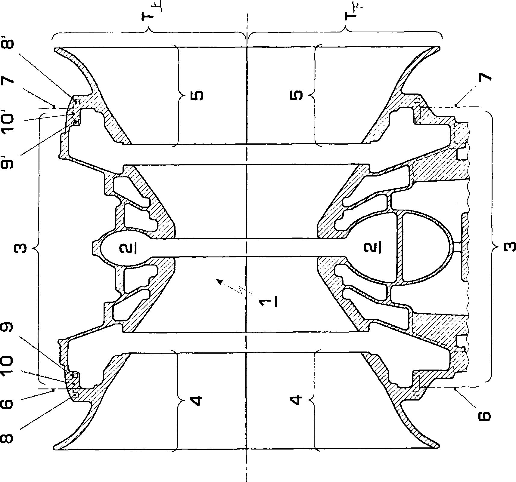
[0018] Part a) shows the longitudinal section of the inner casing of the low-pressure steam turbine, the inner casing is composed of the upper half casing T of the turbine 上 and lower shell T 下 composition. Assume that the two turbine half-shells T 上 and T 下 A fluid-tight mechanically fixed joint along the axial parting surface 1 is known, for example, from DE-OS 1751 055, from which it is known to separate two half-shells of a turbine, in particular a shell of a high-temperature turbine axially Joining technology that connects bodies together.

[0019] The turbine housing shown schematically in sub-figure a) corresponds to the inner housing of a two-flow low-pressure steam turbine, wherein the steam is conveyed radially inward from the inflow chamber 2 in the middle into a working channel in which The steam spreads along the corresponding conically enlarged inner contour of the turbine housing on both axial sides while performing expansion work, so that the rotor unit (no...


PUM


Abstract

A method for producing a turbine casing for a rotating machine is provided. The casing is manufactured by a casting process, and is cast in two casing halves which are separated by a parting plane which passes axially through the turbine casing. Each casing half is first cast in one piece in each case, and each casing half is separated into at least two casing sections which are joined together for forming a casing half in each case.

Description

technical field [0001] The invention relates to a method for manufacturing a turbine casing of a rotating machine obtained by a casting process, wherein the turbine casing is cast separately into two parts which can be separated by a parting surface axially penetrating the turbine casing half shells, and the two half shells are composed of at least two separate shell segments. Background technique [0002] The rotating machine radially surrounds the flow channel along which the working medium spreads axially under the generation of expansion energy, through which the rotor arrangement surrounded by the turbine housing and equipped with the rotor blade set is arranged, the rotating machine's The turbine housing serves as a support structure for the guide vanes, which protrude into the gaps between the guide vane groups arranged on the rotor side. For structural and assembly reasons, the turbine housing is formed from at least two half shells, which are respectively assembled...

Claims


Application Information

Patent Timeline
Patent Type & Authority Applications(China)
IPC IPC(8): B22C9/24F01D25/24
CPCF01D25/24F05D2230/21B22D25/02F05B2230/21Y10T29/49229Y10T29/49826Y10T29/49988Y10T29/4932Y10T29/49236Y10T29/49989Y10T29/49789
Inventor B·格宗齐尔M·费希尔
Owner GENERAL ELECTRIC TECH GMBH
Why Eureka
Try Eureka