
Cage supporting and accepting device and method of hoisting vessel

A technology for stabilizing tanks and containers, which is applied in the field of devices for undertaking and stabilizing tank cages. It can solve the problems of large amount of basic engineering reconstruction, high operation requirements, and cumbersome operations, and achieve the effect of less reconstruction engineering, improved lifting efficiency, and simple operation.

Active Publication Date: 2011-05-11
CHINA UNIV OF MINING & TECH
View PDF0 Cites 0 Cited by
  • Summary
  • Abstract
  • Description
  • Claims
  • Application Information

AI Technical Summary

Problems solved by technology

However, the device still has the following deficiencies in actual use: (1) the operation requirements are high, and the tank stop position is required to be accurate (the error is only 40mm); (2) the operation is cumbersome, and the reverse operation of the winch is required after loading and unloading; It is suitable for the existing electric control system of the winch in my country. If you want to use this device, you must be equipped with a special electric control system from Siemens; (4) The amount of basic engineering transformation is large and the cost is high

Method used


Image

  • Cage supporting and accepting device and method of hoisting vessel
  • Cage supporting and accepting device and method of hoisting vessel
  • Cage supporting and accepting device and method of hoisting vessel

Examples


Embodiment Construction

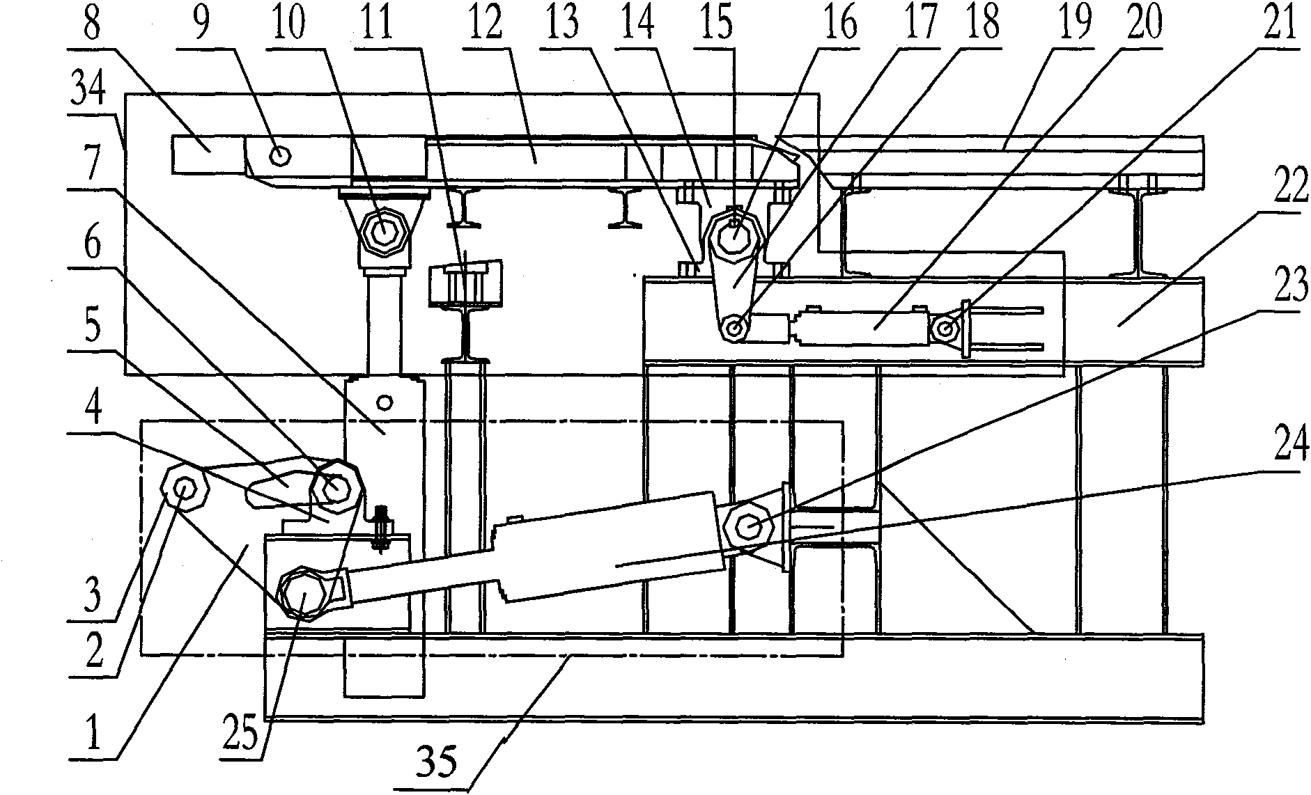
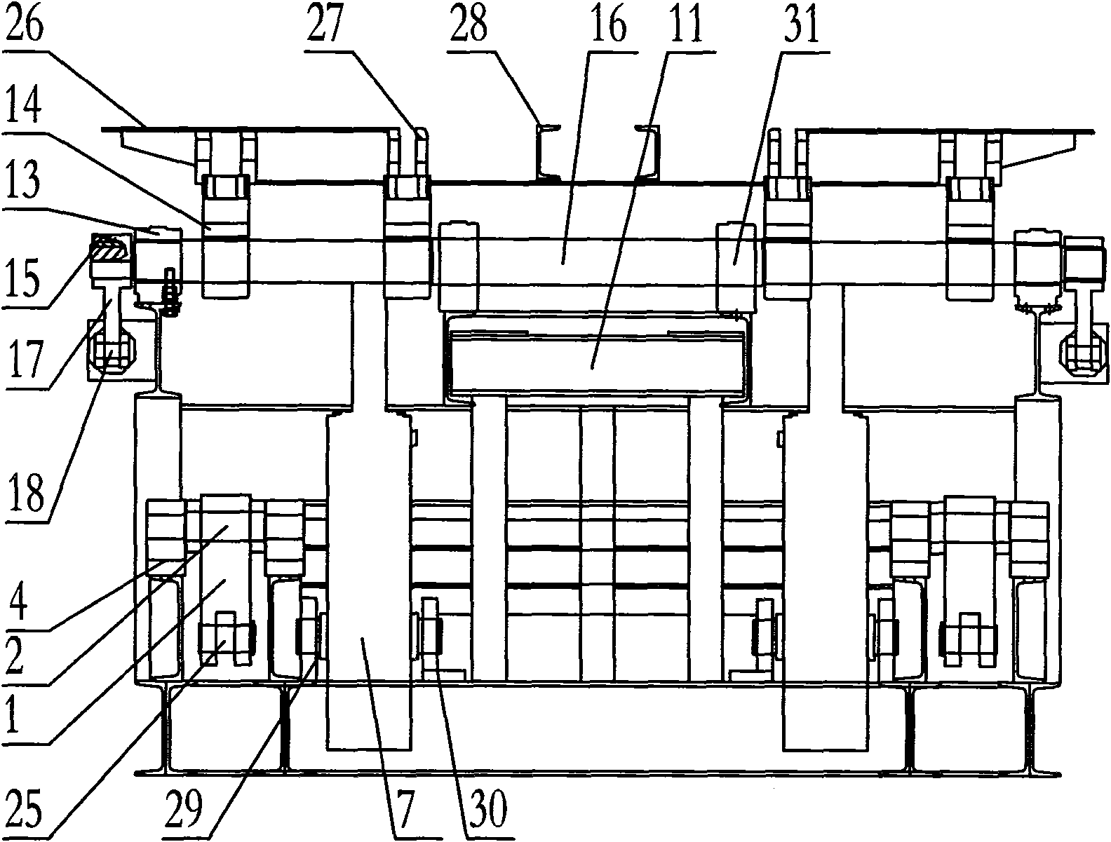
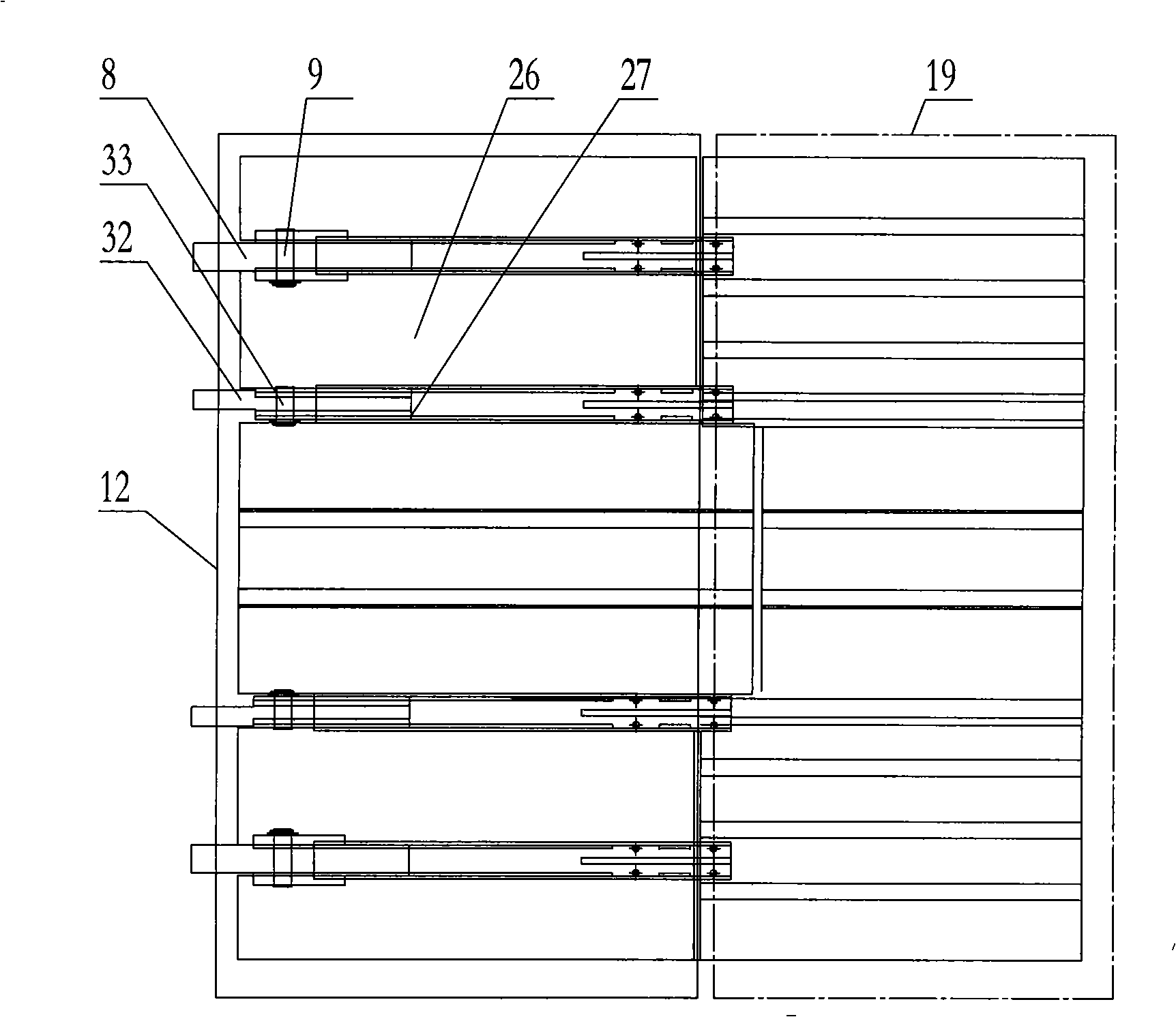
[0028] figure 1 As shown, the tank stabilizing device of the present invention is mainly composed of a frame 22 , a receiving device 35 , a rocker arm connection device 34 and a rocker arm rear platform 19 . The bottom of frame 22 is provided with the receiving device 35 that accepts cage chassis, and the top is provided with the rocking arm connecting device 34 of stabilizing cage, and the afterbody of rocking arm connecting device 34 is provided with rocking arm rear platform 19. The receiving device 35 includes a receiving cylinder 24, supporting claw 1, roller 3, receiving shaft 6, receiving bearing 4 and receiving cylinder seat 23; The rear end of the body is hinged with the receiving cylinder seat 23 through a pin shaft, and the receiving cylinder seat 23 is fixed on the frame 22; the supporting claw 1 is an asymmetric arc surface triangle, and an arc groove 5 is opened at the upper end; the accepting shaft 6 passes through the arc groove 5 is installed on the receiving...


PUM


Abstract

The invention provides a pot supporting and stabilizing device and a method for lifting a container. The device consists of a stander, a carrying device, a rocker arm connecting device and a rocker arm rear platform, wherein the carrying device comprises a carrying hydro cylinder, a supporting claw, a carrying shaft and a carrying bearing; and the rocker arm connecting device comprises a rocker arm platform, a pot stabilizing hydro cylinder, a swing stem, a rocker arm hydro cylinder, a rocker arm shaft housing, an internal rocker arm bearing, an external rocker arm bearing, an internal pot stabilizing block and an external pot stabilizing block. When a cage does not reach an upper position and a lower position a mouth of a well for stopping the pot, the rocker arm platform is in a state of upwardly swinging and uplifting, and the supporting claw is in a pullback state; when the cage reaches the position of stopping the pot and is stopped, the carrying hydro cylinder elongates to push the supporting claw to carry the cage; according to the weight of the equipment going out and in the cage, whether the rocker arm hydro cylinder or the pot stabilizing hydro cylinder operates is selected, the rocker arm platform is fallen to the horizontal position to compress the upper surface of the cage chassis so as to stabilize the cage; after the equipment goes in and out the cage, the rocker arm hydro cylinder extends to push the swing stem to uplift the rocker arm platform, the carrying hydro cylinder contracts to pull back the supporting claw so that the cage conveniently runs up and down. The invention has simple structure, high stability for carrying the cage, high safety and high stability.

Description

technical field [0001] The invention relates to a tank supporting and stabilizing device and method for a lifting container, in particular to a device and method suitable for receiving and stabilizing a cage during the loading and unloading process of a large lifting container in a mine. Background technique [0002] During the loading and unloading process of the mine hoist, the cradle receiving device is required to connect the inner and outer lanes, so as to avoid the impact load directly acting on the cage, and avoid the excessive elongation of the steel wire rope due to excessive load. When the small-load equipment enters and exits the cage, the elastic expansion and contraction of the steel wire rope hanging the cage is small, and the equipment can enter and exit the cage smoothly. And when large-load equipment, such as heavy-duty flatbed truck (maximum mass about 39 tons) enters and exits the cage, the elastic elongation of the steel wire rope hanging the cage is larg...

Claims


Application Information

Patent Timeline
Patent Type & Authority Patents(China)
IPC IPC(8): B66B17/16
Inventor 朱真才陈义强邵杏国陈利强王雷杨建奎訾斌鲍久圣陈光柱曹国华钮磊李一磊
Owner CHINA UNIV OF MINING & TECH
Learn More