Aluminum alloy fixed-distance cutting device

A cutting device, aluminum alloy technology, applied in positioning devices, metal processing equipment, metal processing machinery parts, etc., can solve the problems of leaving more, increasing the labor intensity of operators and operating risks, etc.

Pending Publication Date: 2019-02-01
湖南千源铝业有限公司
View PDF0 Cites 2 Cited by
  • Summary
  • Abstract
  • Description
  • Claims
  • Application Information

AI Technical Summary

Problems solved by technology

[0002] Aluminum alloy profiles are the most widely used non-ferrous metal structural materials in modern society, especially the application of tubular aluminum alloys in building materials, furniture and other adjacent areas; the process of using aluminum alloy profiles to produce aluminum alloy doors and windows and other products needs to be based on market demand. Cut the aluminum alloy profiles into different lengths. The existing method is to place the aluminum alloy profiles on the processing table of the cutting equipment, and then use the cutting sheet to cut the aluminum alloy profiles. During the cutting process, in order to ensure the cutting quality, it is necessary to The operator holds the end of the aluminum alloy profile. Although this method can avoid undesirable phenomena such as uneven cutting surface caused by the shaking of the aluminum alloy profile during the cutting process, it also increases the labor intensity and operation risk of the operator; at the same time In order to cut aluminum alloy profiles of a specified length, it is necessary to mark the outer surface of the aluminum alloy profiles before cutting. During the cutting process, use the method of visual alignment to place the marks directly under the cutting piece for cutting. Before cutting, it is necessary to leave More allowance to prevent the error in the visual alignment process from causing insufficient length after cutting, so that after the cutting is completed, reprocessing is required to obtain the aluminum alloy profile of the specified length

Method used


Image

  • Aluminum alloy fixed-distance cutting device
  • Aluminum alloy fixed-distance cutting device
  • Aluminum alloy fixed-distance cutting device

Examples


Embodiment Construction

[0022] In order to enable those skilled in the art to better understand the technical solution of the present invention, the present invention will be described in detail below in conjunction with the accompanying drawings. The description in this part is only exemplary and explanatory, and should not have any limiting effect on the protection scope of the present invention. .

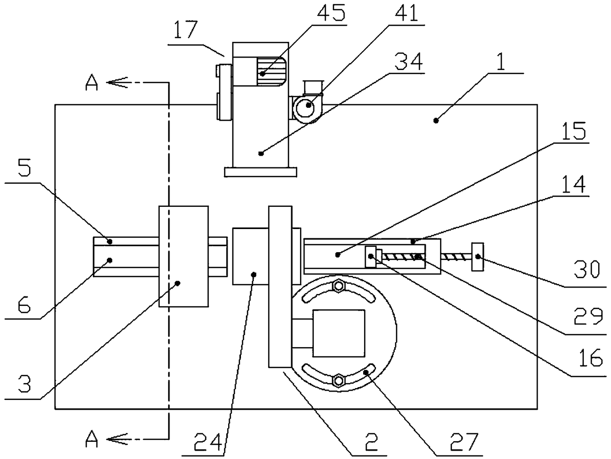
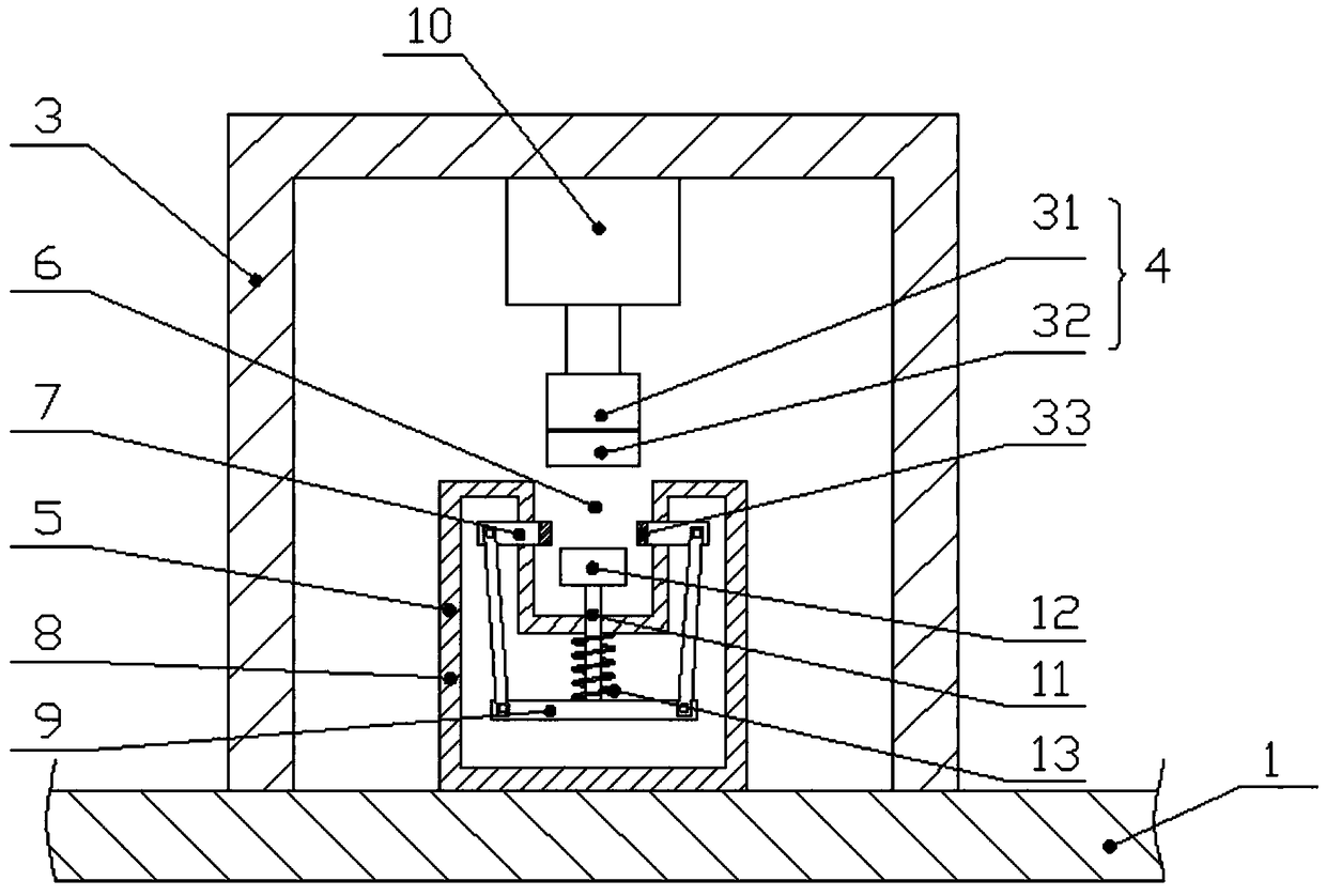
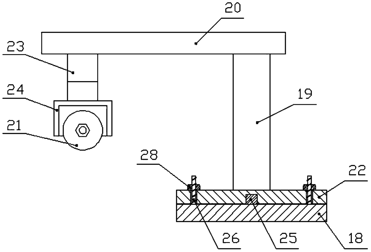
[0023] like Figure 1-Figure 5 As shown, the specific structure of the present invention is: it includes a processing table 1, the upper end surface of the processing table 1 is a horizontal plane, the upper end of the processing table 1 is provided with a cutting mechanism 2, and the upper end of the processing table 1 is on the side of the cutting mechanism 2 A support 3 is provided, and the support 3 is provided with a clamping and pushing device 10 for pushing the vertical clamping plate 4 up and down. The clamping and pushing device 10 can adopt a cylinder, an oil cylinder, etc., and the vertical ...


PUM


Abstract

The invention discloses an aluminum alloy fixed-distance cutting device. The aluminum alloy fixed-distance cutting device comprises a machining table top; a cutting mechanism is arranged at the upperend of the machining table top; a bracket is arranged the part, on one side of the cutting mechanism, of the upper end of the machining table top; a clamping pushing device for pushing a vertical clamping plate to ascend and descend is arranged on the bracket; a placing seat is arranged below the vertical clamping plate; a placing groove is formed in the upper end of the placing seat; a horizontalclamping plate and a bearing plate are arranged on the placing groove; an object carrying plate opposite to the placing seat is arranged at the part, on the other side of the cutting mechanism, of the upper end of the machining table top; an object carrying groove in the same direction as the placing groove is formed in the upper end of the object carrying plate; a positioning plate which can slide horizontally and be locked is arranged in the object carrying groove; and a dust suction device is arranged at the upper end of the machining table top. The aluminum alloy fixed-distance cutting device can clamp an aluminum alloy profile to prevent the aluminum alloy profile from shaking in the cutting process; and at the same time, fixed-distance cutting on the aluminum alloy profile is convenient.

Description

technical field [0001] The invention relates to the field of aluminum alloy processing, in particular to an aluminum alloy fixed-distance cutting device. Background technique [0002] Aluminum alloy profiles are the most widely used non-ferrous metal structural materials in modern society, especially the application of tubular aluminum alloys in building materials, furniture and other adjacent areas; the process of using aluminum alloy profiles to produce aluminum alloy doors and windows and other products needs to be based on market demand. Cut the aluminum alloy profiles into different lengths. The existing method is to place the aluminum alloy profiles on the processing table of the cutting equipment, and then use the cutting sheet to cut the aluminum alloy profiles. During the cutting process, in order to ensure the cutting quality, it is necessary to The operator holds the end of the aluminum alloy profile. Although this method can avoid undesirable phenomena such as un...

Claims


Application Information

Patent Timeline
IPC IPC(8): B23D79/00B23Q3/06B23Q11/00
CPCB23D79/00B23Q3/064B23Q11/0046
Inventor 赵文德
Owner 湖南千源铝业有限公司
Why Eureka
Try Eureka