
High-efficiency air-conditioner heat exchanger

A technology for heat exchangers and air conditioners, applied in evaporators/condensers, lighting and heating equipment, refrigeration components, etc., can solve problems such as poor effect and failure, and achieve the effect of uniform temperature and uniform distribution

Active Publication Date: 2009-07-15
HISENSE HOME APPLIANCES GRP CO LTD
View PDF10 Cites 2 Cited by
  • Summary
  • Abstract
  • Description
  • Claims
  • Application Information

AI Technical Summary

Problems solved by technology

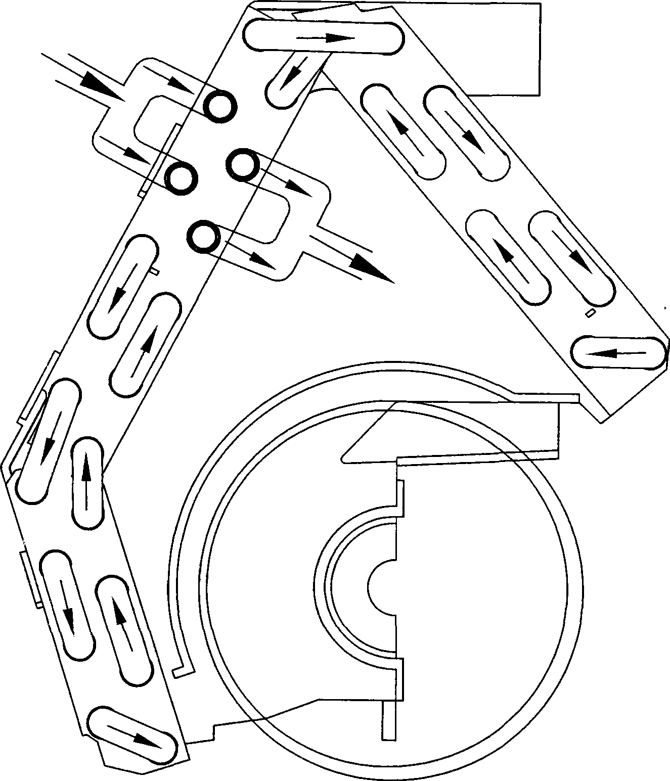
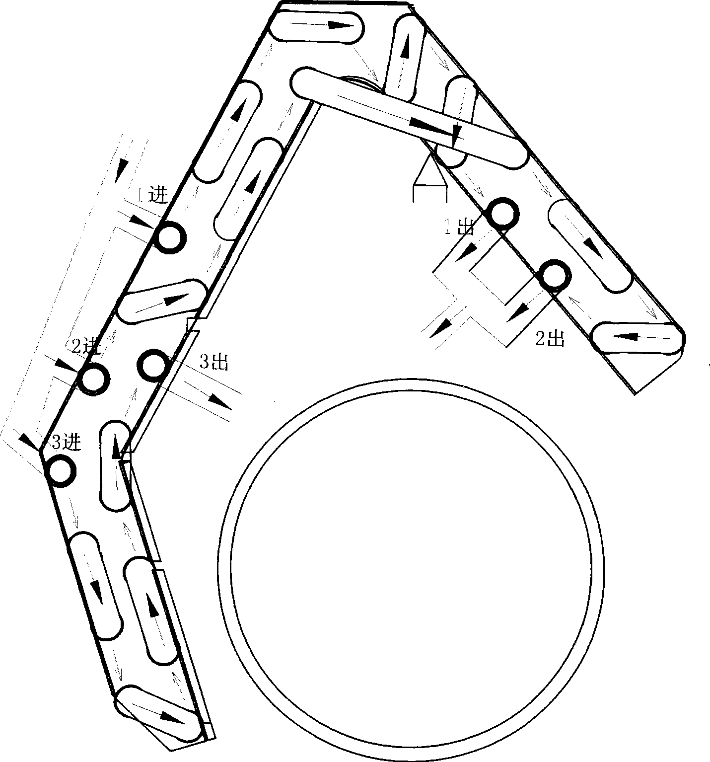
The second route of refrigerant uses 4 U-tubes from the superior field of air volume, and 2 U-tubes from the last inferior field. When the air volume is worse than that of the first route, one more U-pipe is used, and the effect is the worst.
This flow path is successful in improving cooling energy efficiency, but fails in harsh high humidity conditions

Method used


Image

  • High-efficiency air-conditioner heat exchanger
  • High-efficiency air-conditioner heat exchanger
  • High-efficiency air-conditioner heat exchanger

Examples


Embodiment Construction

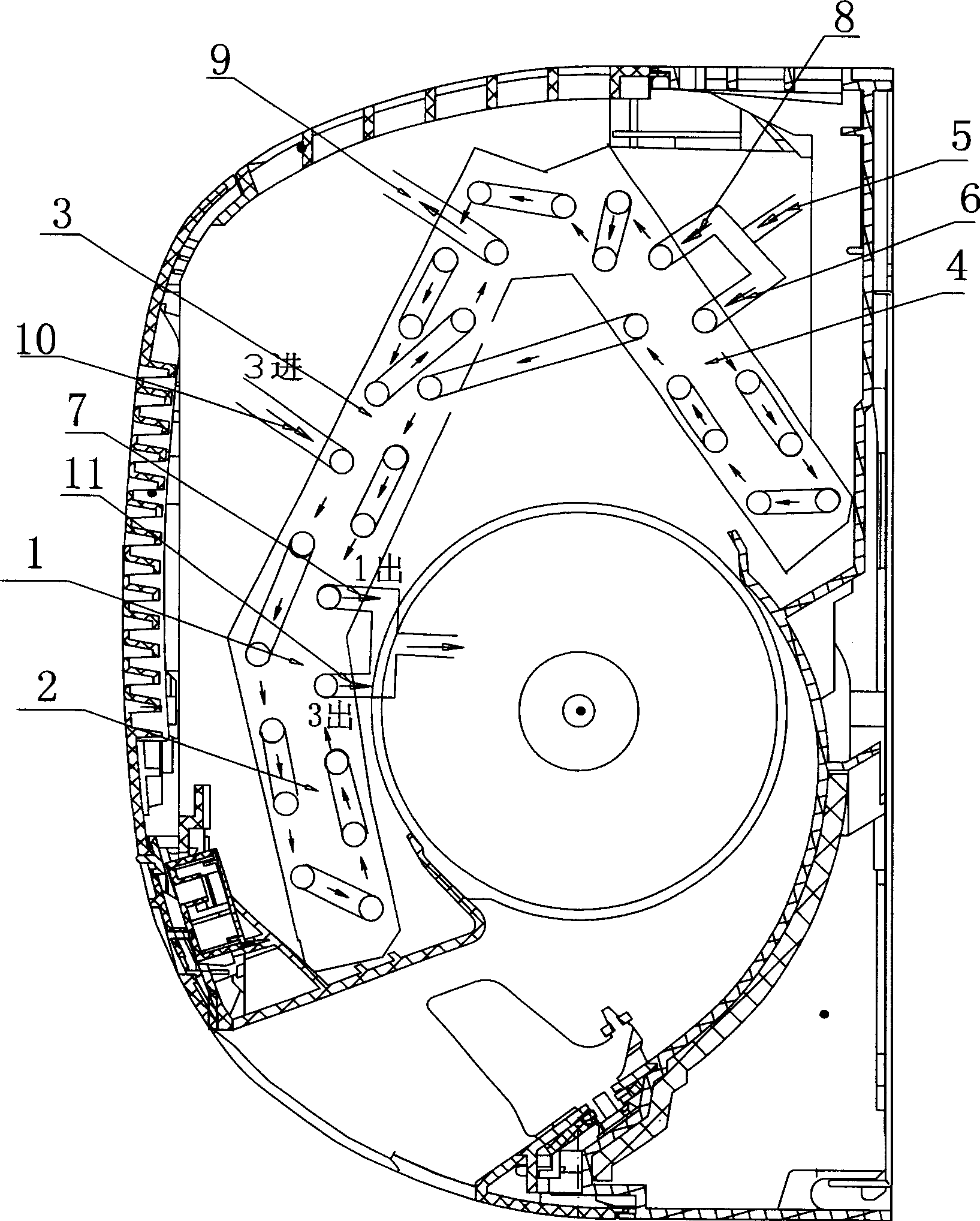
[0012] like image 3 As shown, a high-efficiency air-conditioning heat exchanger 1, when the refrigerant enters the high-efficiency air-conditioning heat exchanger 1, it is divided into three paths, the first path of refrigerant enters from the middle position 6 of the third fold 4 of the heat exchanger, Walk two U-tubes and then go up two U-tubes, jump to the middle of the second fold 3 of the heat exchanger, walk two U-tubes and come out from the first outlet 7 of the heat exchanger. The second route of refrigerant also enters from the middle position 8 of the third fold 4 of the heat exchanger, walks up the distance of one and a half U tubes, and then walks to the second fold 3 of the adjacent heat exchanger to the top of the heat exchanger 1 , and then go down 2 U tubes, and then turn back 1 U tube and come out from the second exit 9. The third fold 4 of the heat exchanger is all on the evaporation temperature like this. The third refrigerant enters from the middle posit...


PUM


Abstract

The invention discloses an efficient air-conditioning heat exchanger, which comprises three refrigerant flow paths. A first path of refrigerant enters from a middle position (6) of a third fold (4) of the heat exchanger, flows through two U pipes downwards and then two U pipes upwards, jumps to the middle of a second fold (3) of the heat exchanger, and flows out from a first outlet (7) of the heat exchanger after finishing flowing through the two U pipes; a second path of refrigerant enters from a middle position (8) of the third fold (4) of the heat exchanger, flows through one and half U pipe upwards and then flows to the second fold (3) of an adjacent heat exchanger to the uppermost part of the heat exchanger, then flows through two U pipes downwards, and retraces to one U pipe to flow out from a second outlet (9); a third path of refrigerant enters from a middle position (10) of the second fold (3) of the heat exchanger, finishes flowing through a first fold (2) of the heat exchanger, and flows out from a third outlet (11) at the lower part of the second fold (3) to converge the refrigerant from the other two paths. The efficient air-conditioning heat exchanger splits stream evenly and has higher heat transfer efficiency.

Description

technical field [0001] The invention relates to the technical field of air conditioners, in particular to the technical field of air conditioner heat exchangers. Background technique [0002] Today, when energy-saving air conditioners are becoming more and more popular, more people focus on improving the energy efficiency ratio of air conditioners under the condition of limited cost. At present, in order to achieve a higher energy efficiency ratio in the development of fixed-frequency air conditioners, it is necessary to use a small compressor and increase the configuration of the two devices. However, with the increase of the two devices and the increase of refrigerant, it is necessary to adopt a multi-flow path method to improve the heat exchange efficiency. And then there are too many flow paths, and the flow is often uneven. Some two adjacent U-shaped tubes have a difference of 6°C, and one U-shaped tube is overheated by evaporation, while the other is overcooled. If s...

Claims


Application Information

Patent Timeline
IPC IPC(8): F25B39/00
Inventor 曹全杨晓明杨金刚
Owner HISENSE HOME APPLIANCES GRP CO LTD
Learn More