Integral time constant calibration method

A technology of integration time and calibration method, applied in the field of integrator, can solve the problems of difficult measurement of integrator parameters, no one is practical and reliable, and achieve the effect of clear steps, fast measurement process and simple operation

Inactive Publication Date: 2009-07-15
INST OF PLASMA PHYSICS CHINESE ACAD OF SCI
View PDF0 Cites 6 Cited by
  • Summary
  • Abstract
  • Description
  • Claims
  • Application Information

AI Technical Summary

Problems solved by technology

[0003] However, the calibration of the integral time constant has always been a major problem in the determination of integrator parameters, and there is no practical and reliable method

Method used


Image

  • Integral time constant calibration method
  • Integral time constant calibration method
  • Integral time constant calibration method

Examples


Embodiment Construction

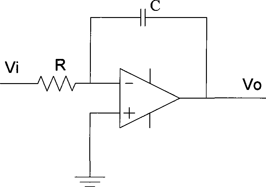
[0014] A kind of integral time constant calibration method is characterized in that comprising the following steps:

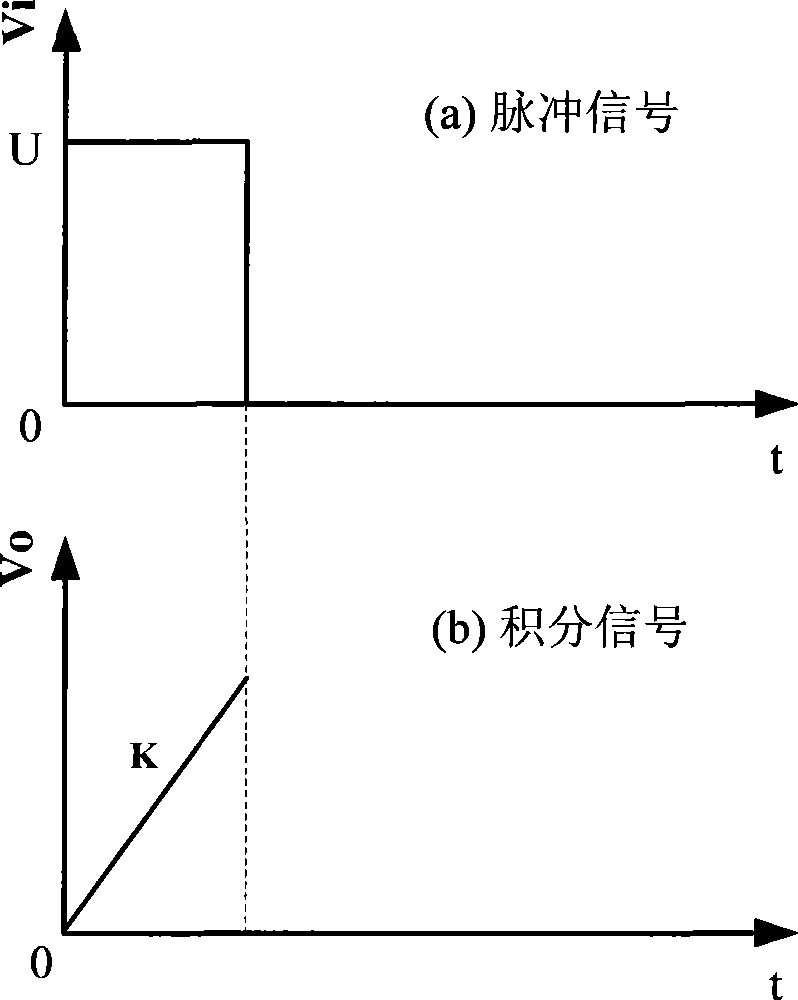
[0015] (1) A pulse signal is given to the input terminal of the integrator, the amplitude is U, integrated by the integrator, and the integral output curve is obtained;

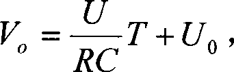
[0016] (2) According to the formula, after time T, the integrated output voltage v o = U RC T + U 0 , Where R is the integrator resistance, C is the integrator capacitance, T is the integration time, U 0 is the initial voltage of the integrator, then the integral slope K can be calculated from the integral output curve.

[0017] (3) The slope of the integral output curve K = V 0 - U 0 ...


PUM


Abstract

The invention discloses an integral time constant calibration method which is characterized by comprising following steps: (1) a pulse signal with an amplitude of U is given to an input end of an integrator, and the integrator integrates the pulse signal to obtain an integral output curve; (2) according to the formula, after a time T, an integral output voltage is that V=(U/RC)T+U, wherein R is an integrator resistance, C is an integrator capacitance, T is an integral time, and U is an integrator initial voltage, thereby the integral slope K can be calculated by the integral output curve; (3) the slope of the integral output curve is that K=(V to U)/T=(U/RC), thereby an integral time constant is that t=RC=U/K, wherein U is the amplitude of the pulse signal, K is the slope of the integral output curve, U and K can be calculated by the formula, and the integral time constant t can be calculated by substituting U and K. The method of the invention has simple operation and clear steps, the according formulas are all known physical formulas, and no special devices are needed in the method of the invention. And the method of the invention has rapid measurement process and accurate measured value, and is convenient for technicist to use.

Description

Technical field: [0001] The invention relates to the field of integrators, in particular to a method for calibrating an integral time constant. Background technique: [0002] Traditional analog basic integrating circuits, such as figure 1 As shown, it is mainly composed of integral resistance, integral capacitance and operational amplifier, and the integral resistance and capacitance form the integral time constant τ=RC. However, the integral capacitance and resistance are not ideal, so there is an error between the actual integral time constant and the ideal value, which will inevitably have a great impact on the control of the experimental calculation. Therefore, it is effective to calibrate the integral time constant and grasp its exact value. Improve the precision of the experiment. [0003] However, the calibration of the integral time constant has always been a major problem in the determination of integrator parameters, and there is no practical and reliable method ...

Claims


Application Information

Patent Timeline
Patent Type & Authority Applications(China)
IPC IPC(8): G06G7/18
Inventor 王勇季振山罗家融吴一纯李实
Owner INST OF PLASMA PHYSICS CHINESE ACAD OF SCI
Why Eureka
Try Eureka