Electronic trip device case for a circuit breaker, electronic trip device and assembly method thereof

A technology for tripping devices and housings, applied in the field of tripping, which can solve problems such as cumbersome manufacturing process of circuit breakers, unoptimized connection of electronic tripping devices, etc.

Active Publication Date: 2009-07-15
SCHNEIDER ELECTRIC IND SAS
View PDF14 Cites 10 Cited by
  • Summary
  • Abstract
  • Description
  • Claims
  • Application Information

AI Technical Summary

Problems solved by technology

[0007] Despite various designs as described in document EP 0 991 095, electronic tripping devices are not optimized and

Method used


Image

  • Electronic trip device case for a circuit breaker, electronic trip device and assembly method thereof
  • Electronic trip device case for a circuit breaker, electronic trip device and assembly method thereof
  • Electronic trip device case for a circuit breaker, electronic trip device and assembly method thereof

Examples


Embodiment Construction

[0024] The invention will be described below according to a preferred embodiment including a selection of tripping device 200, these optional items may be omitted if desired. Alternatives will be apparent to those skilled in the art, and the different parts listed should not be considered as essential for the purpose of seeking protection. To simplify the illustrations, some elements that are optional for the purposes of the present invention are not included in all figures.

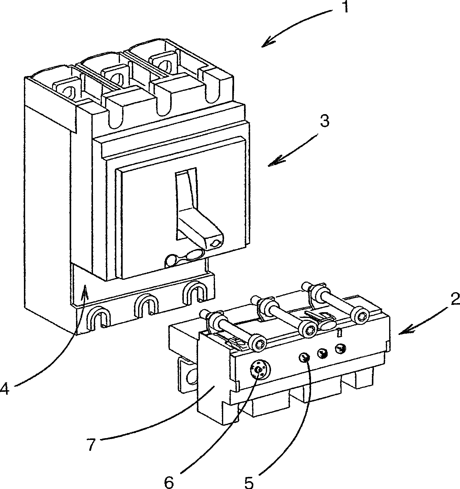
[0025] Furthermore, the tripping device according to the invention can be mounted on different existing "moulded case" switch units, especially those operating between 16 and 630 A, regardless of the number of poles, even though the shown embodiment concerns Yu Rufigure 1 The electronic tripping device of the three-pole circuit breaker 1 shown includes three pairs of contacts to interrupt the current of each phase of the three-phase electricity.

[0026] Finally, to simplify the description of the prefe...


PUM


Abstract

An electronic module for a trip device has been optimised so as to integrate the known functionalities, in particular threshold parameter setting, current measurements, voltage taps, read-out display and communication. An electromagnetic actuator is further present in the electronic module to optimise breaking of the associated circuit breaker. The space occupation constraints inherent to location of the trip device in existing switchgear units have been respected.

Description

technical field [0001] The invention relates to tripping of switchgear by electronic processing. More particularly, the method relates to an electronic trip device capable of being integrated in an existing switchgear and acting on the contacts of the switchgear by means of an incorporated electromagnetic actuator. In addition, the electronic module of the tripping device also includes known function blocks, in particular threshold value parameter setting, current measurement, test connector, display and communication function blocks. [0002] The invention also relates to a housing for an electronic trip device having a design optimized for maximum compactness. The invention also relates to a tripping device and a method of assembly thereof, which is simplified despite the density of integrated functional blocks. Background technique [0003] as described in document FR 2 696 275, and as figure 1 Schematically shown, the molded case circuit breaker 1 comprises a trip dev...

Claims


Application Information

Patent Timeline
IPC IPC(8): H01H71/02H01H71/08H01H71/74
CPCH01H71/125H01H2071/006H01H2071/0242H01H2071/0292H01H71/7409
Inventor 亨利·贝洛托
Owner SCHNEIDER ELECTRIC IND SAS
Why Eureka
Try Eureka