External calibration method for phase variable power detecting array antenna

An array antenna and power detection technology, applied in antennas, electrical components, etc., can solve problems such as poor applicability, and achieve the effects of low cost, simple calculation, and low hardware environment requirements

Active Publication Date: 2009-07-15
中国航天科技集团公司第五研究院第五〇四研究所
View PDF0 Cites 40 Cited by
  • Summary
  • Abstract
  • Description
  • Claims
  • Application Information

AI Technical Summary

Problems solved by technology

This method must be calibrated in four quadrat

Method used


Image

  • External calibration method for phase variable power detecting array antenna
  • External calibration method for phase variable power detecting array antenna
  • External calibration method for phase variable power detecting array antenna

Examples


Embodiment Construction

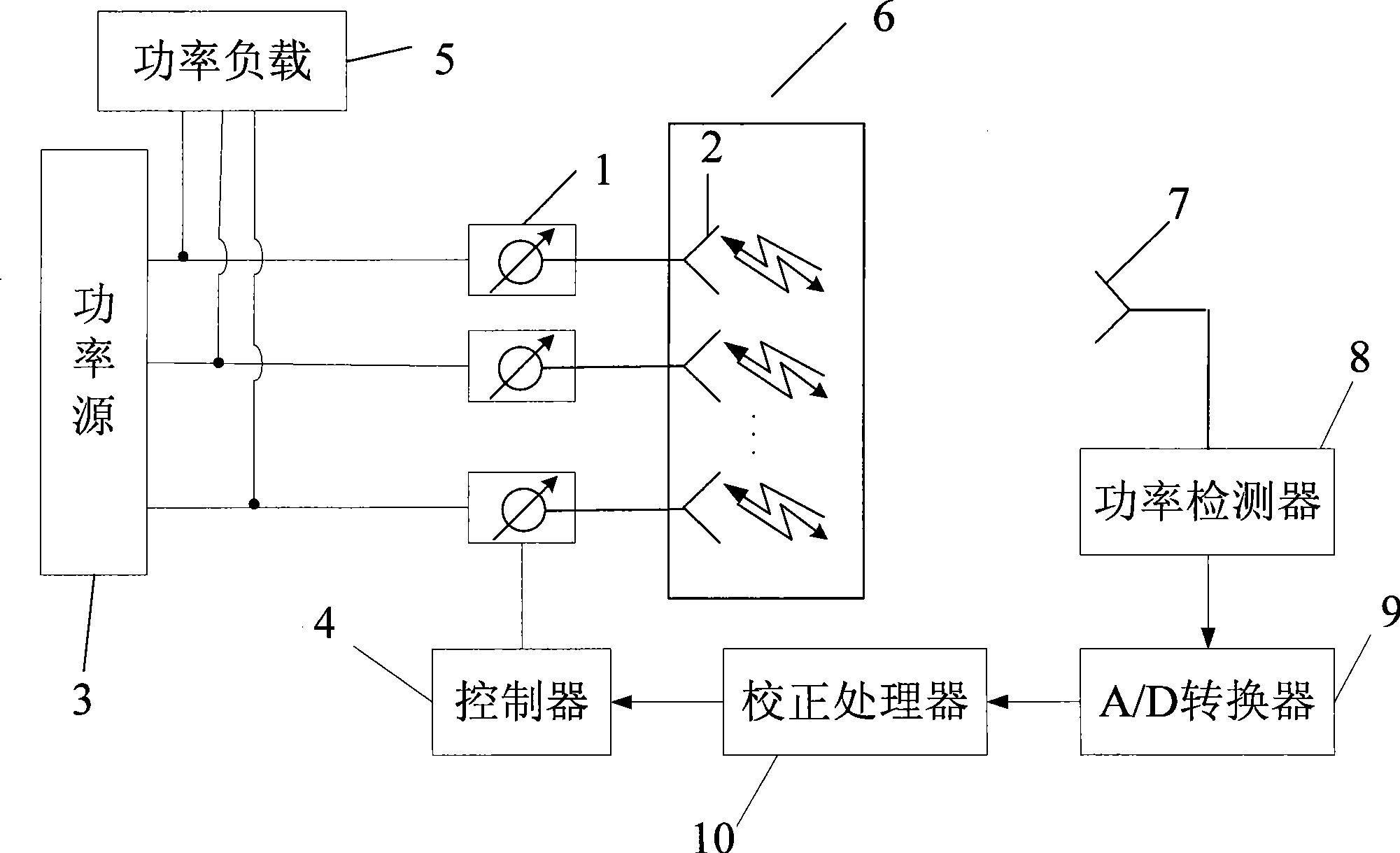
[0041] Such as figure 1 As shown, during calibration of the present invention, an auxiliary antenna 7 needs to be added for receiving array signals or transmitting reference signals. The array antenna 6 is the antenna to be tested, the phase shifter 1, the power source 3, the controller 4, the power load 5, and the power detection The device 8, the A / D converter 9 and the correction processor 10 are the original auxiliary equipment of the array antenna 6. The array antenna 6 is composed of many antenna elements 2, and a phase shifter 1 is connected after each antenna element 2, and each antenna element 2 can be used to transmit or receive electromagnetic signals.

[0042] When the array antenna 6 is in the transmitting mode, the power source 3 feeds each antenna unit channel through the corresponding phase shifter 1 to transmit the array signal. The power source 3 divides a signal into multiple paths through a power divider to feed each antenna unit. The controller 4 controls the...


PUM


Abstract

A phase alterable power detected array antenna external calibration method is an external calibration algorithm of an array antenna channel amplitude and phase consistency calibration. The array antenna comprises a plurality of antenna units, the phase of each antenna unit signal is controllable, and each antenna unit signal stacks and forms the array antenna signal. In order to realize the calibration of the array antenna, the invention alters the state of an alterable digital phase shifter connected with each antenna unit, obtains a response to the external calibration signal of the array antenna, forms a positive definite or overdetermined equation corresponding the response of a specific channel at multiple different states, obtains the relative amplitude and the relative phase corresponding to the reference signal of the channel by solving the equation, thus obtains an phase-amplitude consistency error of each channel of the array, thereby realizing calibration.

Description

Technical field [0001] The invention relates to an array antenna, in particular to an external calibration method of the array antenna. Background technique [0002] The array antenna is composed of many antenna elements, and each element is fed with a signal of a certain amplitude and phase to form a specific beam and realize beam scanning. Generally, the amplitude of the unit signal is adjusted by controlling the attenuator of the connection unit to form the required beam, and the phase of the unit signal is controlled by changing the phase of the phase shifter of the connection unit to achieve beam scanning. [0003] In order to accurately control the beam, the actual phase response of each element of the antenna needs to be known. However, the phase response is affected by various unavoidable errors and manufacturing tolerances and is a function of time and temperature, so calibration is used to determine the phase response error and compensate for the phase. Similarly, the a...

Claims


Application Information

Patent Timeline
IPC IPC(8): H01Q3/38
Inventor 田步宁敬红勇
Owner 中国航天科技集团公司第五研究院第五〇四研究所
Why Eureka
Try Eureka