

Accelerometer calibration method and device based on coherent light vision optical flow detection
A technology of accelerometer and coherent light, which is applied in the direction of measuring device, speed/acceleration/shock measurement, speed/acceleration/shock measurement equipment testing/calibration, etc., can solve problems such as limiting practicality, and achieve simple and low-cost implementation. The effect of low, high measurement accuracy
- Summary
- Abstract
- Description
- Claims
- Application Information
AI Technical Summary
Problems solved by technology
Method used
Image

Examples
Embodiment 1
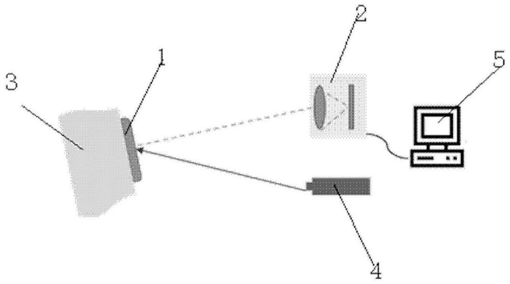
[0079] see image 3 , the device mainly includes: a vibration table 3, a measured accelerometer 1, a camera 2, a small laser 4, and a host computer 5. The measured accelerometer 1 is fixed on the vibrating table 3, and the vibrating table 3 is used to provide test excitation motion for the measured accelerometer 1; the small laser 4 is used to generate coherent light; the camera 2 is used to obtain the scattered light on the surface of the measured accelerometer 1 spot image; the host computer 5 is used to process the calibration information and complete the calibration.
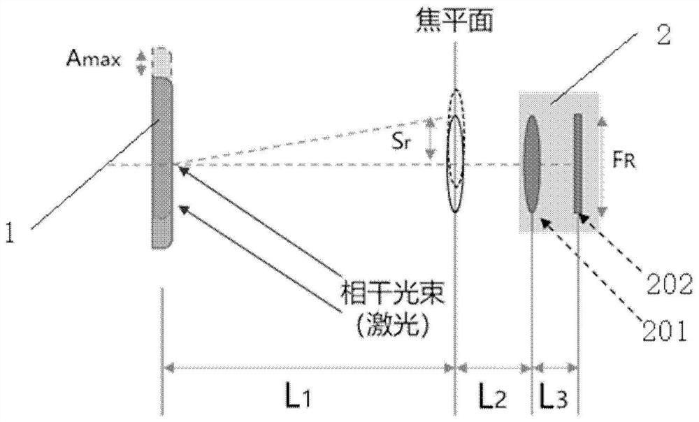
[0080] Step a: use the following parameters to complete the arrangement of the accelerometer calibration device in this embodiment: Sr=50mm, Fr=21mm, Amax=50mm, L3=45mm, L2=75mm, L1=425mm;
[0081] Step b: The small laser, the camera and the vibrating table are turned on at the same time, and the laser light emitted by the small laser is projected on the surface of the measured accelerometer for diffuse ref...
Embodiment 2
[0085] Figure 5 It is a schematic diagram of the device for implementing the method of the present invention. The device mainly includes: a circuit module 6, a measured accelerometer 1 embedded in the circuit module 6, a micro camera 2, a small laser 4, and a host computer 5. The measured accelerometer 1 is fixed on the circuit module 6, and the circuit module 6 is rigidly connected with the measured accelerometer 1; the small laser 4 is used to generate coherent light; the micro camera 2 is used to obtain the speckle image on the surface of the measured accelerometer 1; The upper computer 5 is used to process calibration information and complete calibration.
[0086] The calibration method in this embodiment mainly includes the following steps:
[0087] Step A: Use the following parameters to complete the arrangement of the accelerometer calibration device in this embodiment: Sr=5mm, Fr=3.096mm, Amax=30mm, L3=2mm, L2=2.1mm, L1=50mm:
[0088] Step B: Use the plumb method to...
PUM
 Abstract
Description
Claims
Application Information