Security device

An anti-counterfeiting device and optical element technology, applied in the direction of printing, information-bearing cards, printed matter, etc., can solve the problems of interfering with the eyes to verify the clear and transparent area, and achieve the effect of increasing the difficulty of forgery, easy identification and memory

Inactive Publication Date: 2009-07-15
DE LA RUE INT LTD
View PDF17 Cites 14 Cited by
  • Summary
  • Abstract
  • Description
  • Claims
  • Application Information

AI Technical Summary

Problems solved by technology

In such devices, however, the image is visible in reflected light, interfering with the eye's verification of the presence of clear transparent areas

Method used


Image

  • Security device
  • Security device
  • Security device

Examples


Embodiment Construction

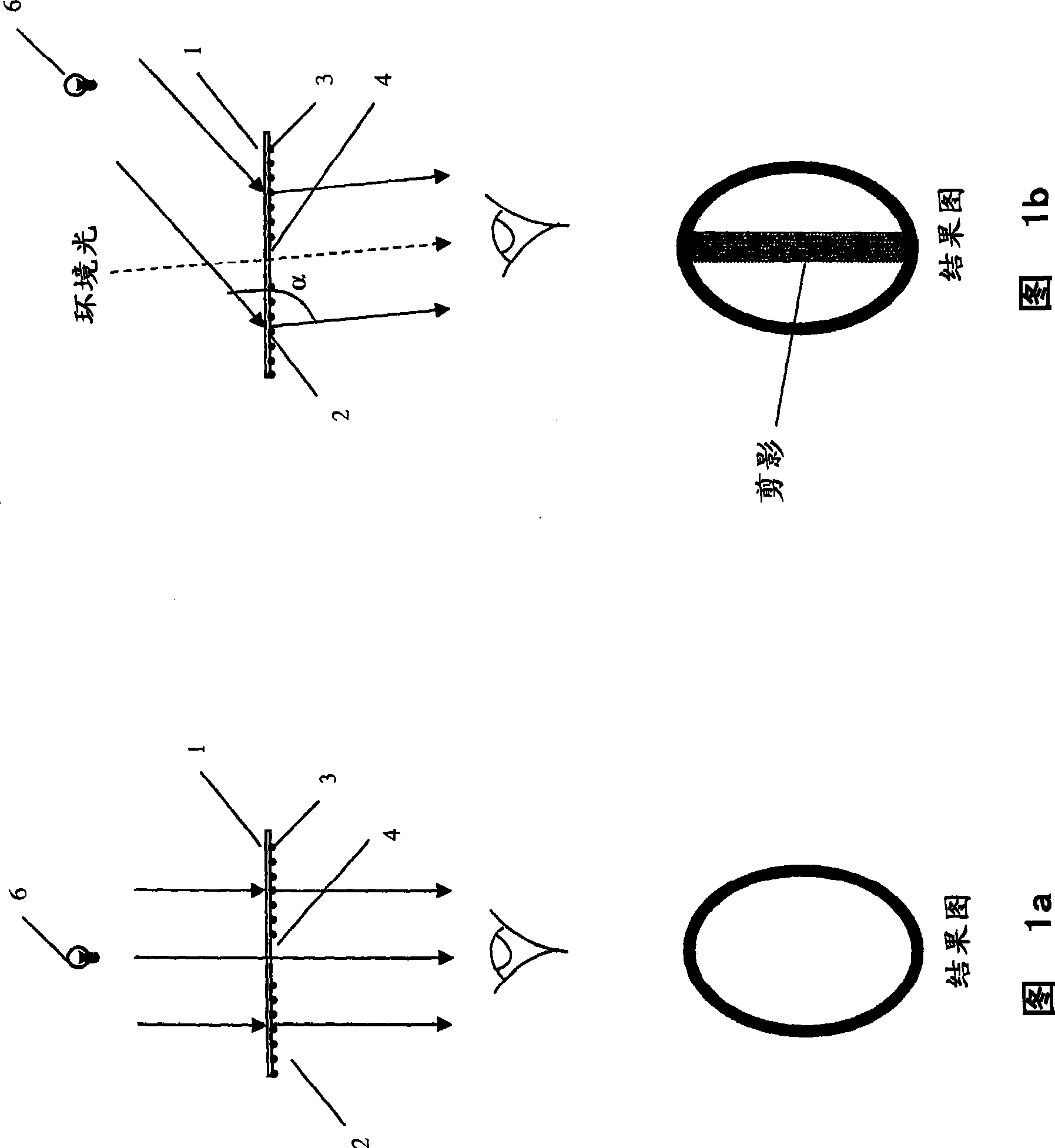
[0027] The first embodiment of an anti-counterfeiting device according to the present invention is as follows: figure 1 A and 1B are shown. The device comprises a base transparent area 1 into which optical elements 2, 3 have been molded in respective spaced parts. The non-embossed part 4 is located between the optical elements 2,3. In this case, the non-embossed portion 4 defines the image under certain viewing conditions.

[0028] When the device is directly backlit so that a light source 6 with an intensity higher than the ambient light level is in line with the device and the observer, the intensity of the transmitted light through the optical elements 2, 3 and the non-refractive region 4 is critical to the viewer. presented substantially the same to the latter, so that the transparent regions appear substantially transparent and featureless (see figure 1 Result plot in a).

[0029]When the device is shaken away from the light source 6 ( figure 1 B) so that when the ob...


PUM


Abstract

A security device comprises a substrate having a transparent region (1). At least one optical element (2, 3) is provided in part of the transparent region, the optical element causing an incident off-axis light beam transmitted through the optical element to be redirected away from a line parallel with the incident light beam whereby when the device is viewed in transmission directly against a backlight, the presence of the optical element cannot be discerned but when the device is moved relative to the backlight such that lines of sight from the viewer to the transparent region and from the transparent region to the backlight form an obtuse angle (a) at which redirected light is visible to the viewer, a contrast is viewed between the part of the transparent region including the optical element and another part of the transparent region. When the security device is viewed in reflection under diffuse lighting conditions either no contrast can be discerned between the two parts or a different contrast can be discerned between the two parts.

Description

technical field [0001] The invention relates to an anti-counterfeit device and to an anti-counterfeit bill provided with the anti-counterfeit device. Background technique [0002] Various security devices have been proposed in the past to prevent forgery or fraudulent manufacture of security documents. Particularly useful anti-counterfeiting devices are those which are easily authenticated by the user, but which are difficult to manufacture. One example of such a security means is a clear transparent area in an otherwise opaque substrate. The use of clear transparent areas prevents "simple" counterfeiting as color photocopiers and other imaging systems become more popular and the technical quality of color photocopies improves. In addition, the clear transparent area also provides an easily verifiable feature by the public. However, clear transparent regions in opaque substrates are easily forged, for example by drilling a hole in the opaque substrate and then placing a c...

Claims


Application Information

Patent Timeline
Patent Type & Authority Applications(China)
IPC IPC(8): B42D15/00
CPCB42D25/29B42D15/0013
Inventor R·怀特曼
Owner DE LA RUE INT LTD
Why Eureka
Try Eureka