Locking device of cap

A cap clamping and capping technology, which is applied in the direction of capping containers, packaging, capping, etc., can solve the problem of unreliable clamping, clamping teeth and mating teeth that cannot obtain clamping force, and large working hours and cost issues

Inactive Publication Date: 2009-07-15
S&B FOODS +1
View PDF0 Cites 0 Cited by
  • Summary
  • Abstract
  • Description
  • Claims
  • Application Information

AI Technical Summary

Problems solved by technology

[0003] The structure of arranging a plurality of mating teeth with small angular intervals in a circular shape, and then matching the tiny clamping teeth on the other side requires precise processing technology, and there are many problems that come with it. For example, it is necessary to use plastic The blow molding process...

Method used


Image

  • Locking device of cap
  • Locking device of cap
  • Locking device of cap

Examples


Embodiment 1

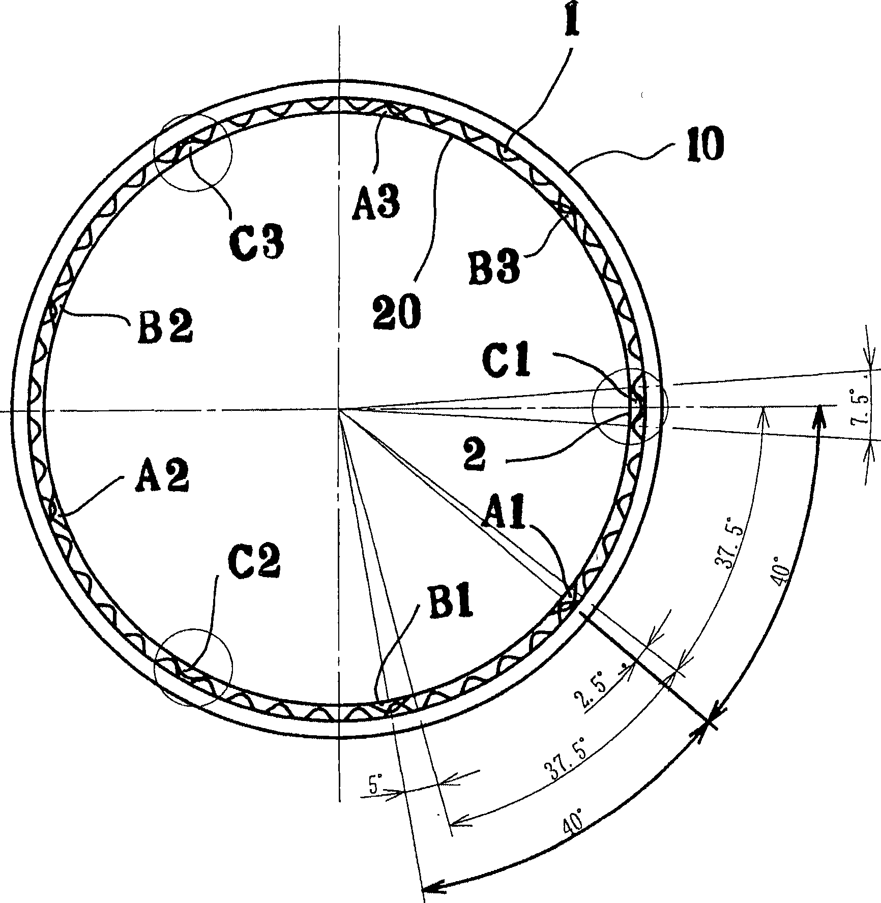
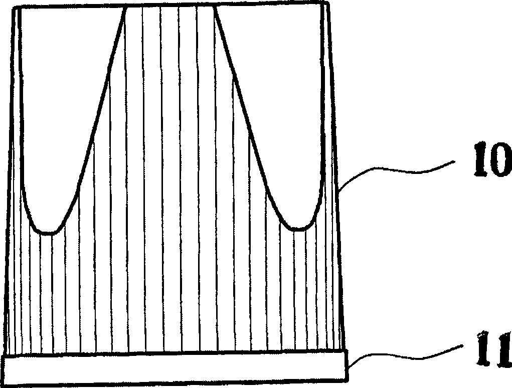
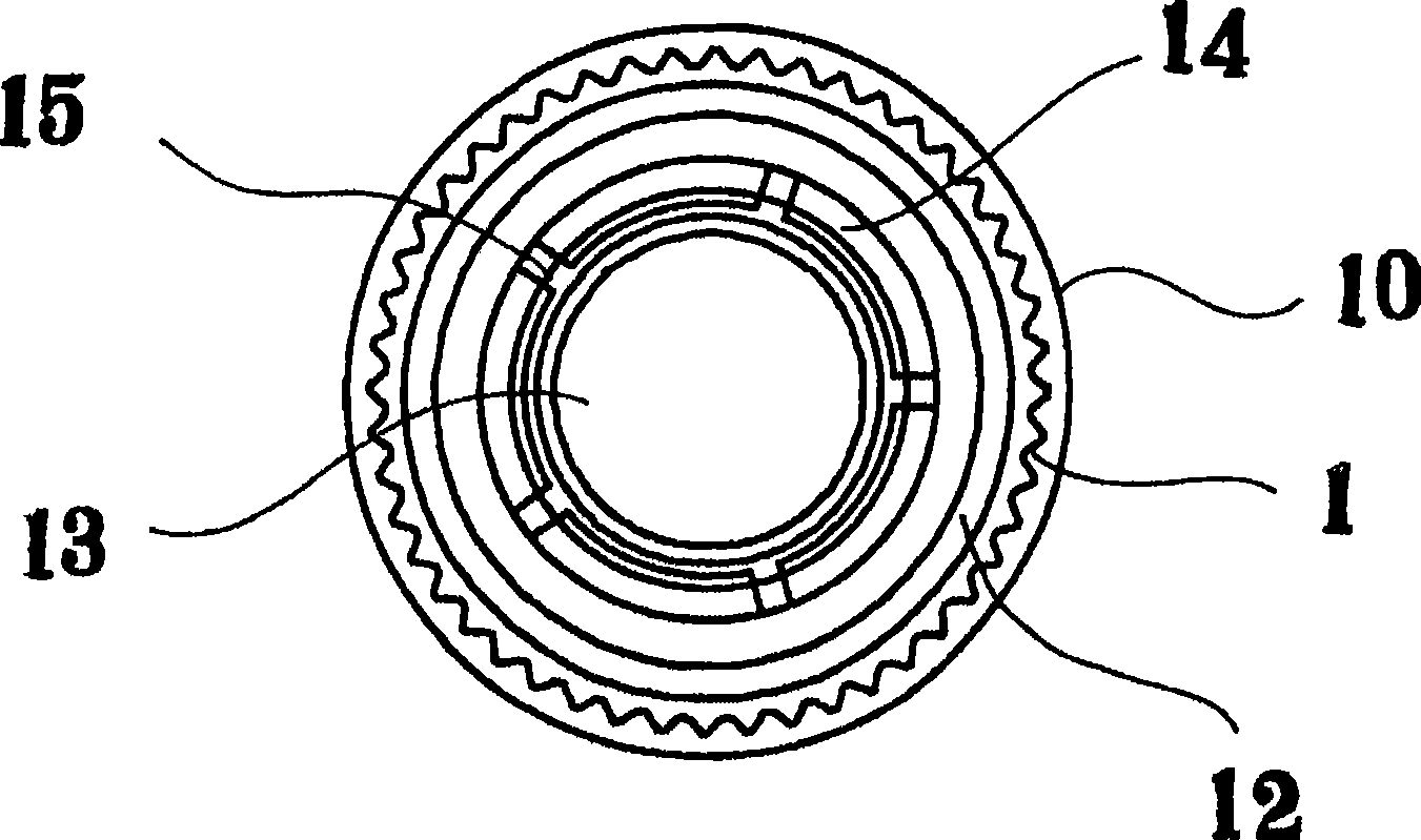
[0072] Figure 11 The cap clamping device of the present invention according to the embodiment has the following structure: when the cap is rotatably mounted to the container, a circumferential mating tooth 1 is provided on either side of the cap and the container, and the clamping tooth 1 provided on the other side is clamped. In the cap clamping device formed by elastically cooperating the tooth 2 with the mating tooth 1, the clamping teeth A, B, C in a group of three are opposite to the central clamping tooth A, and the clamping teeth B, B, C is set to a clamping interval of approximately 1 / 3 pitch P with respect to the 1 pitch P of the mating tooth, so that one of the three snapping teeth A and the adjacent peak and peak of the mating tooth 1 When the center T1 of the valley in the middle cooperates, the other two clamping teeth B and C will contact the inclined surfaces T2 and T3 in the middle of the peak in a balanced manner, so that the mating tooth 1 and the central cl...

Embodiment 2

[0076] In addition, in Figure 12 The cover clamping device has the following structure: three sets of clamping teeth A, B, C are located relative to the central clamping tooth A, and the clamping teeth B and C on both sides are opposite to the first tooth of the mating tooth. The pitch P is set to a clamping interval of approximately 2 / 3 of the pitch P, whereby one A of the three clamping teeth 2 cooperates with the center T1 of the valley between the adjacent peaks and peaks of the mating tooth 1 At the same time, the other two clamping teeth B and C are balanced against the inclined surfaces T2 and T3 in the middle of the peak with elastic force, so that the mating tooth 1 and the central clamping tooth A are close to each other on both sides. Therefore, including the central The clamping teeth A, B, and C of the three groups of clamping teeth are fixedly clamped with the mating tooth 1, so that the cover is kept in a stopped state.

[0077] When one side of the clamping t...

Embodiment 3

[0082] Secondly, in Figure 11 In the embodiment of the above example, among the clamping teeth A, B, and C in groups of three, relative to the clamping tooth A at the center T1, even if the clamping teeth B and C on either side or both sides are set to match the matching teeth 1 The integer multiple of the pitch interval P above 1 pitch is the clamping interval of approximately 1 / 3 pitch interval, which is determined by the Figure 11 The same principle of the embodiment can also obtain the same clamping relationship. Figure 13 In the case of the described embodiment, the cap clamping device of the present invention is set so that when the cap is rotatably mounted to the container, a circumferential mating tooth 1 is provided on either side of the cap and the container, In the cap clamping device in which the provided clamping teeth 2 are elastically matched with the mating teeth 1, a group of three clamping teeth A1, B1, and C1 are located on both sides of the central clam...


PUM


Abstract

Engagement between the engaging teeth at minute intervals on one of a cap and a container and the minute locking teeth on the other is conventionally required for locking the cap to the container at a minute rotational interval, but they may be unlocked to prevent a positive locking, and a precise machining technology is required. Furthermore, it is difficult to provide a locking device at the neck or shoulder portion of a container by blow molding of plastic. In the locking device of a cap for rotary-setting a cap (10) over a container (20) through elastic engagement between the circumferential engaging teeth (1) provided on one of the cap(10) and the container (20) and the locking teeth (2) provided on the other, a set of three locking teeth (2) is arranged such that the locking teeth (B1, C1) located on the opposite sides of a central locking teeth (A1) have a pitch substantially equal to one-third or two-thirds of the integral multiples of the pitch of the engaging teeth.

Description

technical field [0001] The invention relates to a cap clamping device for rotatably mounting and clamping a cap on a container. Background technique [0002] All the time, there are known many lid clamping devices that are mounted on the container in rotation and clamped, especially in order to clamp the lid with a small rotational angle interval, it is necessary to have a small angular interval on either side of the lid or the container. A plurality of mating teeth on one side are arranged in a circular shape, and then the tiny clamping teeth arranged on the other side are matched with it. [0003] The structure of arranging a plurality of mating teeth with small angular intervals in a circular shape, and then matching the tiny clamping teeth on the other side requires precise processing technology, and there are many problems that come with it. For example, it is necessary to use plastic The blow molding processing of the container requires many techniques such as the nec...

Claims


Application Information

Patent Timeline
IPC IPC(8): B65D41/04
CPCB65D41/0471
Inventor 前田隆大山昌文氏原克人大迫弘文河田良夫
Owner S&B FOODS
Why Eureka
Try Eureka