Electroluminescent emission device for optical transmission in free space

A transmission device and free space technology, applied in the direction of free space transmission, electroluminescent light source, transmission system, etc., can solve the problems of being expensive and lacking the main advantages of free space light transmission

Inactive Publication Date: 2009-07-15
齐爱克斯托克资产有限责任公司
View PDF3 Cites 5 Cited by
  • Summary
  • Abstract
  • Description
  • Claims
  • Application Information

AI Technical Summary

Problems solved by technology

[0007] According to the known methods and devices, the problem of the manner in which the signal to be transmitted is transmitted to the light-emitting diodes has not been addressed in a satisfactory manner for all applications, since the use of two different wirings is obviously more complex than that used for lighting only Traditional wiring of luminaires is more expensive
In order to use only one type of wiring, one might expect to use a radio link to carry the signal to be transmitted to each luminaire, but this solution loses the main advantage of free-space optical transmission, which is that it does not use the radio spectrum

Method used


Image

  • Electroluminescent emission device for optical transmission in free space

Examples


Embodiment Construction

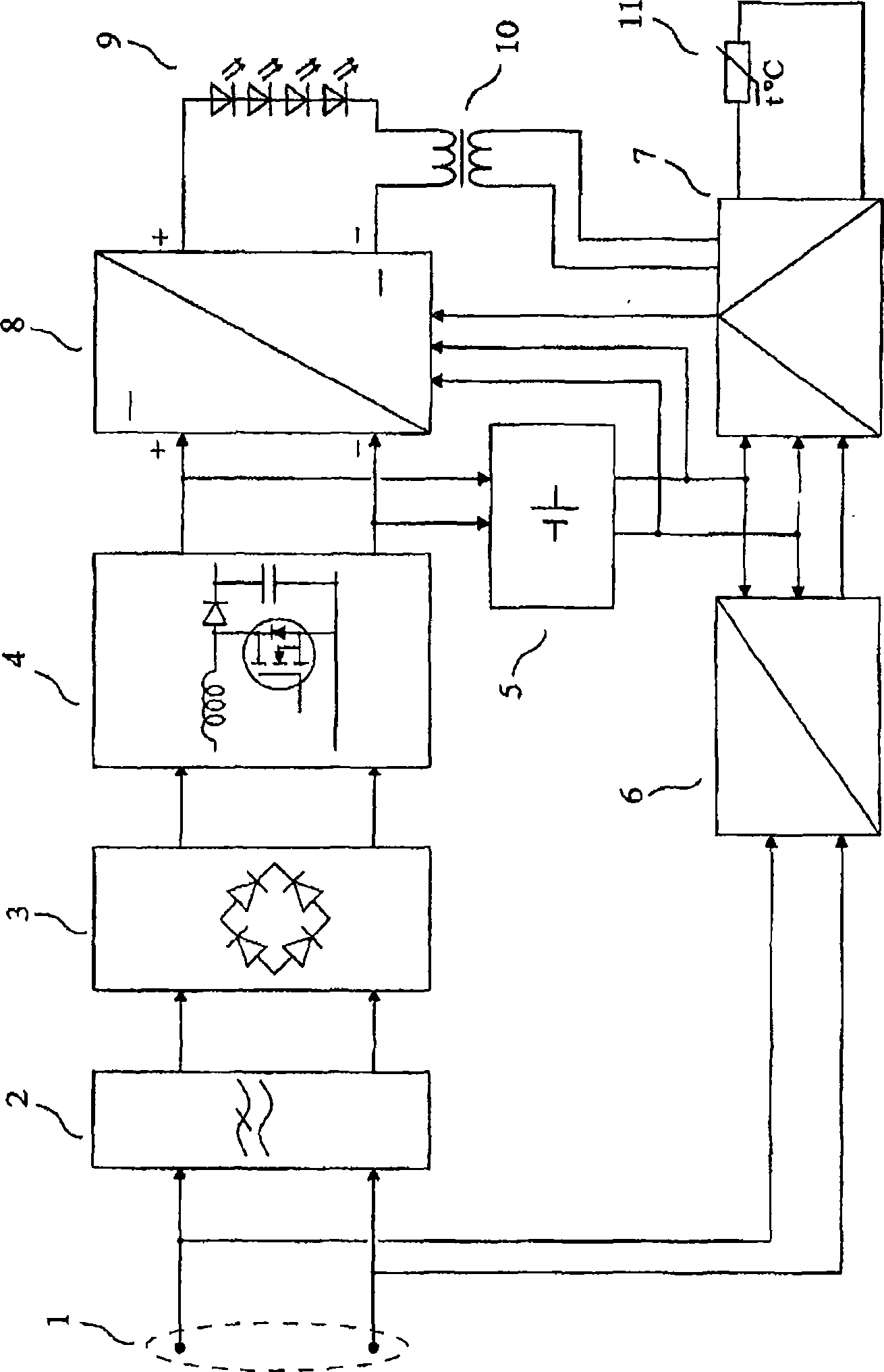
[0026] The example of the device of the invention given by way of non-limiting example makes it possible to show more clearly the other characteristics of the invention, figure 1 The middle table shows the device according to the invention with its input (1) connected to an AC energy distribution system. The power supply filter (2) can effectively reduce the conducted electromagnetic interference generated by the power supply circuit at a frequency higher than 150 Hz according to the rules on electromagnetic compatibility. The power supply circuit includes a rectifier (3), a power factor correction circuit (4), an auxiliary power supply (5) and a direct current-direct current (DC-DC) converter (8). The power factor correction circuit (4) well known to those skilled in the art is a non-isolated auxiliary converter. It draws a sine wave current from the power supply. It therefore provides low emitted harmonic currents in accordance with EMC regulations. It also provides prese...


PUM


Abstract

The invention relates to an emission device for transmission through space, using electromagnetic waves in the infrared range and / or visible range and / or ultraviolet range that are produced by one or more light-emitting diodes. The device is connected via its input terminals (1) to an energy distribution network. A mains filter (2) reduces the electromagnetic interference produced by the power circuits, which comprise a rectifier (3), a power-factor correction circuit (4), an auxiliary power supply (5) and a DC / DC converter (8). The DC / DC converter (8) has its output connected to several series-connected light-emitting diodes (9). An assembly for receiving the transmissions via energy distribution network lines (6) delivers demodulated signals applied to the control circuit (7), which delivers the current setpoint of the DC / DC converter (8) and the modulated current applied to the light-emitting diodes (9) through the modulation transformer (10), according to the demodulated signals and the temperature measured by a temperature sensor (11). The light produced is modulated according to the demodulated signals.

Description

technical field [0001] The invention relates to a transmission device for light transmission through space using electromagnetic waves in the infrared and / or visible and / or ultraviolet bands generated by one or several electroluminescent diodes. Background technique [0002] Hereinafter, the word "light" shall mean electromagnetic radiation, which may include visible light and / or infrared and / or ultraviolet light. Hereinafter, the expression "electroluminescent diode" denotes any type of diode capable of generating electroluminescent light. Such electroluminescent diodes may be, for example, infrared electroluminescent diodes, phosphorous-containing high-power incandescent electroluminescent diodes, organic electroluminescent diodes, and the like. [0003] In French Patent Application No. 0409939 entitled "Dispositif d'émission pour la transmission optique enespace libre" (Lighting device for free-space optical transmission) and "Transmitting device for free-space optical t...

Claims


Application Information

Patent Timeline
Patent Type & Authority Applications(China)
IPC IPC(8): H04B10/10H04B3/54H05B33/00H01L33/00H04B10/114H04B10/116
CPCH04B10/1149H04B10/116H05B33/00H04B3/54H04B10/11
Inventor F·布罗伊德E·克拉韦利耶
Owner 齐爱克斯托克资产有限责任公司
Why Eureka
Try Eureka