Exposure head and an image forming apparatus

An exposure head and image technology, applied in the direction of electrical recording technology using charge graphics, optics, equipment using electrical recording technology using charge graphics, etc., can solve the problem of reduced resolution, increased lens spacing, and increased incident light into the lens, etc. question

Inactive Publication Date: 2012-09-26
SEIKO EPSON CORP
View PDF2 Cites 0 Cited by
  • Summary
  • Abstract
  • Description
  • Claims
  • Application Information

AI Technical Summary

Problems solved by technology

However, in the above-mentioned configuration in which the lenses are arranged at predetermined intervals in the longitudinal direction (first direction), if the diameter of the lenses is increased, the pitch of the lenses in the longitudinal direction (first direction) becomes large, which may not be possible. get the desired resolution
That is to say, in the prior art, there is a case where the resolution decreases while increasing the amount of light incident on the lens.

Method used


Image

  • Exposure head and an image forming apparatus
  • Exposure head and an image forming apparatus
  • Exposure head and an image forming apparatus

Examples


no. 1 approach

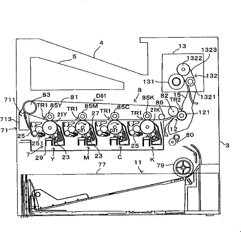
[0073] image 3 It is a diagram showing an example of an image forming apparatus equipped with a line head to which the present invention is applied. in addition, Figure 4yes means image 3 A diagram of the electrical configuration of the image forming apparatus. This device is an image forming device capable of selectively executing a color mode and a monochrome mode in which four colors of black (K), cyan (C), magenta (M), and yellow (Y) are combined. The monochrome mode is a mode in which only black (K) toner is used to form a monochrome image. also, image 3 It is a figure corresponding to the execution of the color mode. In this image forming apparatus, when an image forming command is given from an external device such as a host computer to a main controller MC having a CPU, a memory, etc., the main controller MC gives a control signal and the like to an engine controller EC, and sends a The HC gives video data VD corresponding to the image forming command. In ad...

no. 2 approach

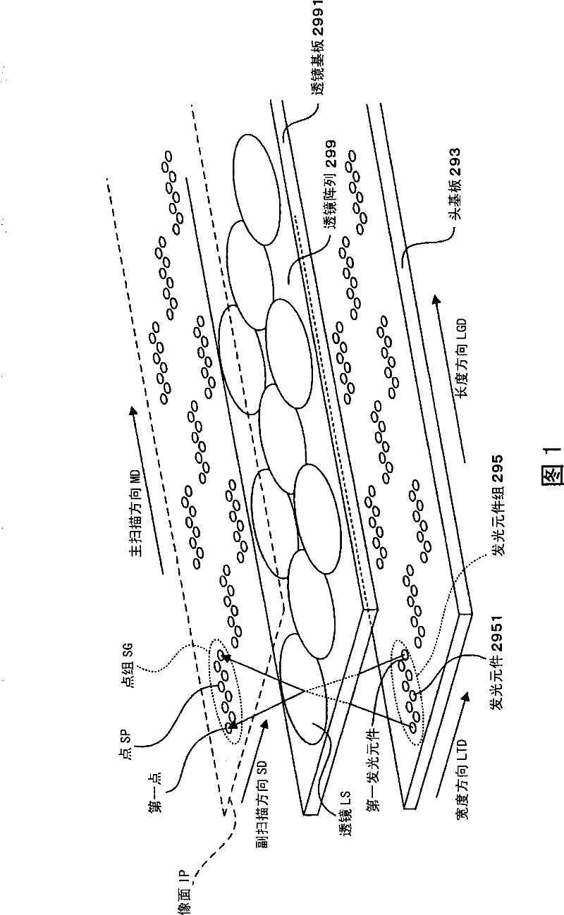
[0118] Figure 13 It is a perspective view which shows the outline of the wire head of 2nd Embodiment. in addition, Figure 14 It is a plan view of the lens array of the second embodiment, and corresponds to a case where the lens array is viewed from the image plane side (the direction Doa side in which light beams travel). also, Figure 14 Each lens LS in is formed on the rear surface 2991-t of the lens array substrate 2991, and this figure shows the structure of the rear surface 2991-t of the lens array substrate. In addition, although the light-emitting element group 295 is described in this figure, this is only to show the corresponding relationship between the light-emitting element group 295 and the lens LS, and does not mean that the light-emitting element group 295 is provided on the rear surface 2991-t of the lens array substrate. Hereinafter, differences between the second embodiment and the first embodiment will be mainly described, and the same parts will be giv...

no. 3 approach

[0124] In addition, in Figure 14In the structure shown, the lens LS-u (first lens, second lens) and the lens LS-m (third lens) are connected to each other, and the distance between the lens LS-u and the lens LS-m will not be enlarged, and the lens LS-u and the lens LS-m can be connected together. A lot of light is incident. In addition, lens LS-m (first lens, second lens) and lens LS-d (third lens) are connected to each other, and a large amount of light can enter the lens without increasing the distance between lens LS-m and lens LS-d. In other words, Figure 14 The structure is a structure capable of suppressing the width of the lens array 299 in the width direction LTD (second direction). As a result, space saving can also be achieved in the width direction LTD in the area where the light emitting elements 2951 are arranged corresponding to the lenses LS on the head substrate 293 . Therefore, in the head substrate 293 on which the light emitting element 2951 is arranged...


PUM


Abstract

An exposure head, includes: a lens array (299) that includes a light transmissive substrate (2991) whose length W1 in a first direction (LGD) is greater than a length W2 thereof in a second direction orthogonal to the first direction, a first lens (LS11) that is arranged on the light transmissive substrate (2991), and a second lens (LS12) that is arranged on the light transmissive substrate (2991) at the first direction (LGD) of the first lens (LS11), the first lens (LS11) and the second lens (LS12) being connected in the first direction (LGD), thereby providing a technology capable of makinga large amount of light upon the lens and realizing excellent exposure.

Description

technical field [0001] The present invention relates to an exposure head and an image forming apparatus using a lens array in which a plurality of lenses are arranged. Background technique [0002] As such a lens array, for example, the lens array of Patent Document 1 is known figure 2 etc., a structure in which a plurality of lenses are arranged at a predetermined pitch in the longitudinal direction. In this lens array, lenses adjacent to each other in the longitudinal direction are arranged at predetermined intervals, and each lens forms an image of incident light. Then, the light formed by each lens exposes a latent image carrier such as a photoreceptor drum to form a latent image. [0003] Patent Document 1: Japanese Unexamined Patent Publication No. 6-278314 [0004] In addition, from the viewpoint of performing good exposure, it is preferable that the amount of light incident on the lens is large. Therefore, for example, enlarging the diameter of the lens is consid...

Claims


Application Information

Patent Timeline
Patent Type & Authority Patents(China)
IPC IPC(8): B41J2/447G03G15/00
Inventor 小泉龙太野村雄二郎宗和健
Owner SEIKO EPSON CORP
Why Eureka
Try Eureka