Lens array, exposure head, and image forming apparatus

A lens array and exposure head technology, applied in the field of lens arrays, can solve the problems of enlarging the lens array and increasing the width of the lens array, etc.

Inactive Publication Date: 2009-07-22
SEIKO EPSON CORP
View PDF2 Cites 1 Cited by
  • Summary
  • Abstract
  • Description
  • Claims
  • Application Information

AI Technical Summary

Problems solved by technology

As a result, the width (that is, the length in the width direction) of th

Method used


Image

  • Lens array, exposure head, and image forming apparatus
  • Lens array, exposure head, and image forming apparatus
  • Lens array, exposure head, and image forming apparatus

Examples


no. 1 approach

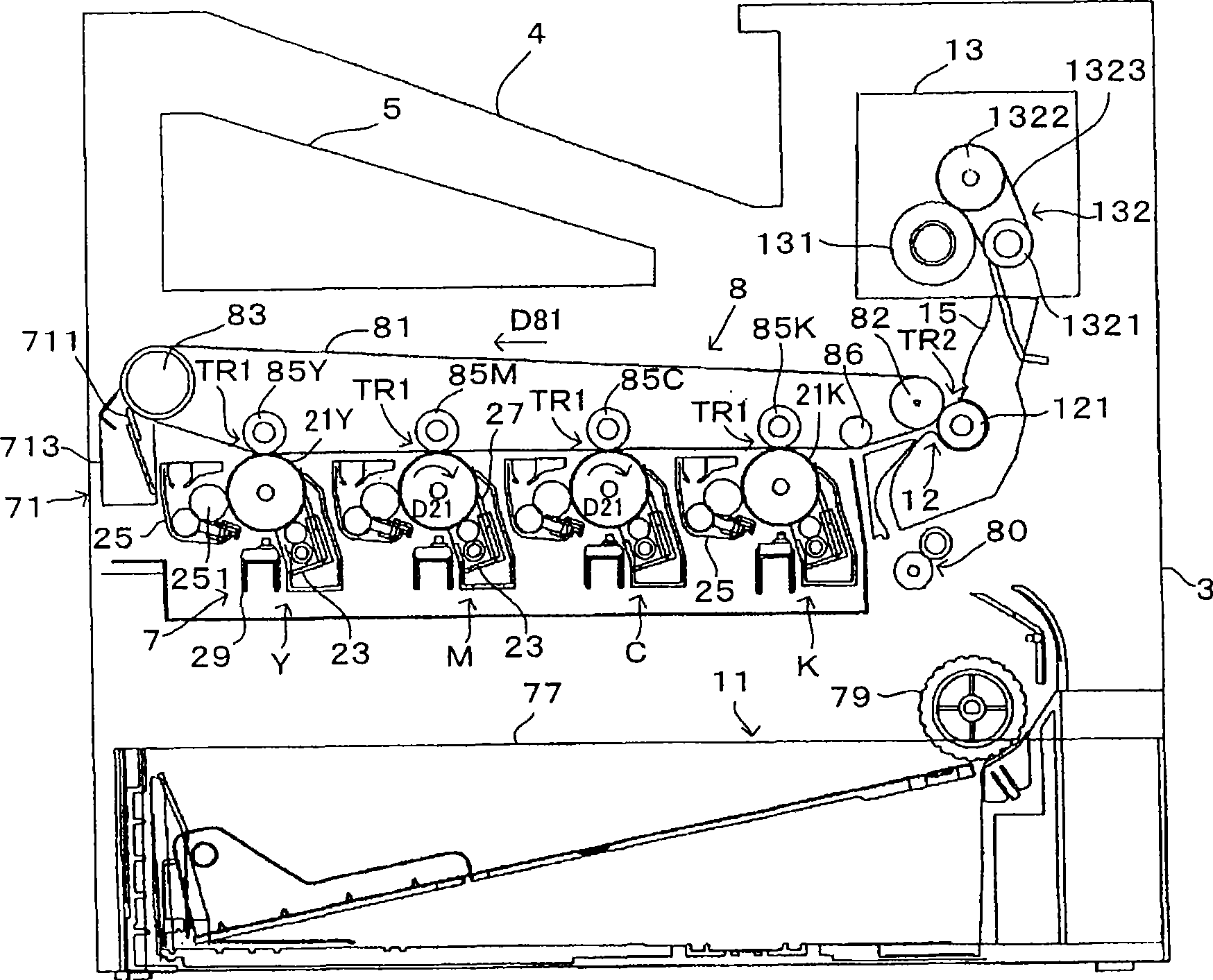
[0072] image 3 It is a diagram showing an example of an image forming apparatus equipped with a line head to which the present invention is applied. also, Figure 4 yes means image 3 A diagram of the electrical structure of the image forming device. This device is an image forming device capable of selectively executing a color mode in which toners of four colors of black (K), cyan (C), magenta (M), and yellow (Y) are superimposed While forming a color image, the monochrome mode forms a monochrome image using only black (K) toner. and, image 3 It is the corresponding drawing when the color mode is executed. In this image forming apparatus, when an image forming command is given from an external device such as a host computer to a main controller MC having a CPU, a memory, etc., the main controller MC sends a control signal, etc. to a motor controller EC, and communicates with the image The video data VD corresponding to the formation command is given to the head contr...

no. 2 approach

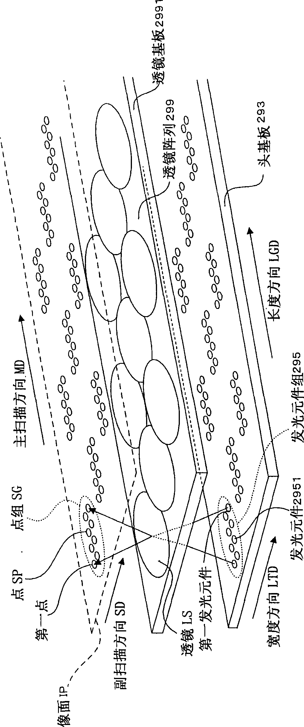
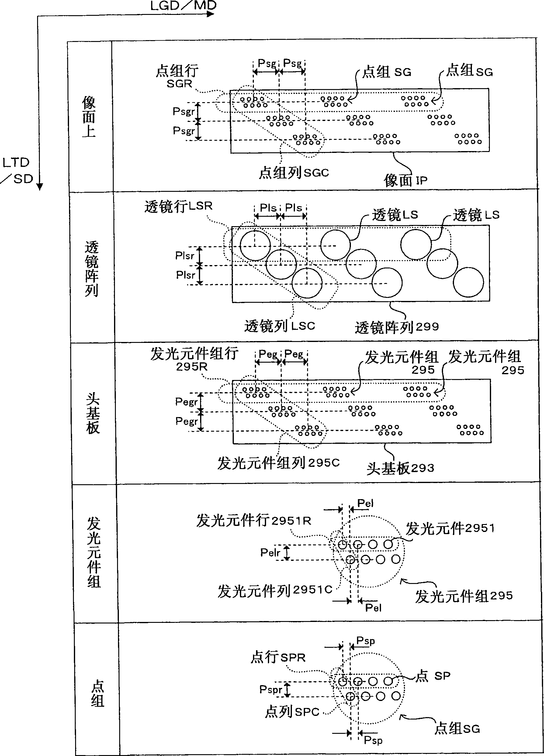
[0117] Figure 13It is a plan view which shows the structure of the lens array which concerns on 2nd Embodiment. The lens array 299 includes a lens array substrate 2991 (light-transmitting substrate) made of glass. In this way, by forming the lens array substrate 2991 from a glass material with a relatively small coefficient of linear expansion, deformation of the lens array 299 due to temperature changes is suppressed. The lens array substrate 2991 has a length W1 in the longitudinal direction LGD, and a width W2 (length W2) in the width direction LTD. In addition, the relationship of length W1>W2 is satisfied, and the lens array substrate 2991 has a long side in the longitudinal direction LGD. On the surface 2991-h of the lens array substrate 2991, a plurality of lenses LS made of photocurable resin (resin material) are formed by the above-mentioned metal mold method. The plurality of lenses LS are two-dimensionally arranged. That is, three lenses LS are arranged in the ...


PUM

PropertyMeasurementUnit
Thicknessaaaaaaaaaa

Abstract

The invention provides a lens array that can cope with exposure with high resolution and can be reduced in size. The lens array includes a light-transmissive substrate (2991) that satisfies the condition W1>W2, where W1 is the length of the light-transmissive substrate in a first direction LGD and W2 is the length of the light-transmissive substrate in a second direction LTD perpendicular to the first direction, a first lens (LS11) that is provided on the light-transmissive substrate (2991), and a second lens (LS21) that is provided on the light-transmissive substrate (2991) on the second direction LTD side of the first lens (LS11). The first lens (LS11) and the second lens (LS21) are connected to each other.

Description

technical field [0001] The present invention relates to a lens array equipped with a plurality of lenses, an exposure head using the lens array, and an image forming apparatus. Background technique [0002] As such a lens array, for example, the lens array of Patent Document 1 is known. figure 2 etc., a plurality of lenses are arranged in a row. In this lens array, each lens forms an image of incident light. Then, the light formed by each lens exposes a latent image carrier such as a photoreceptor drum to form a latent image. [0003] Patent Document 1: Japanese Unexamined Patent Publication No. 6-278314 [0004] In addition, in order to cope with exposure with a higher resolution, a plurality of lenses can be arranged two-dimensionally to form a lens array. That is, in this lens array, in the width direction (second direction) perpendicular to or substantially perpendicular to the longitudinal direction, a plurality of lenses are arranged at mutually different positions...

Claims


Application Information

Patent Timeline
IPC IPC(8): G02B3/00G02B1/04B41J2/447G03G15/04G03G15/01
Inventor 小泉龙太野村雄二郎宗和健井熊健
Owner SEIKO EPSON CORP
Why Eureka
Try Eureka