Fuel injector

一种燃料喷射器、喷嘴体的技术,应用在燃料喷射装置、特殊燃料喷射装置、具有压电元件或磁致伸缩元件的燃料喷射装置等方向,能够解决成本和复杂性影响等问题

Inactive Publication Date: 2009-07-22
DELPHI TECH HLDG SARL
View PDF0 Cites 20 Cited by
  • Summary
  • Abstract
  • Description
  • Claims
  • Application Information

AI Technical Summary

Problems solved by technology

[0015] In all of these systems, separate control and drive systems must be provided to control the selective injection of fluid, which has a significant impact on the cost and complexity of setting up these systems

Method used


Image

  • Fuel injector
  • Fuel injector
  • Fuel injector

Examples


Embodiment Construction

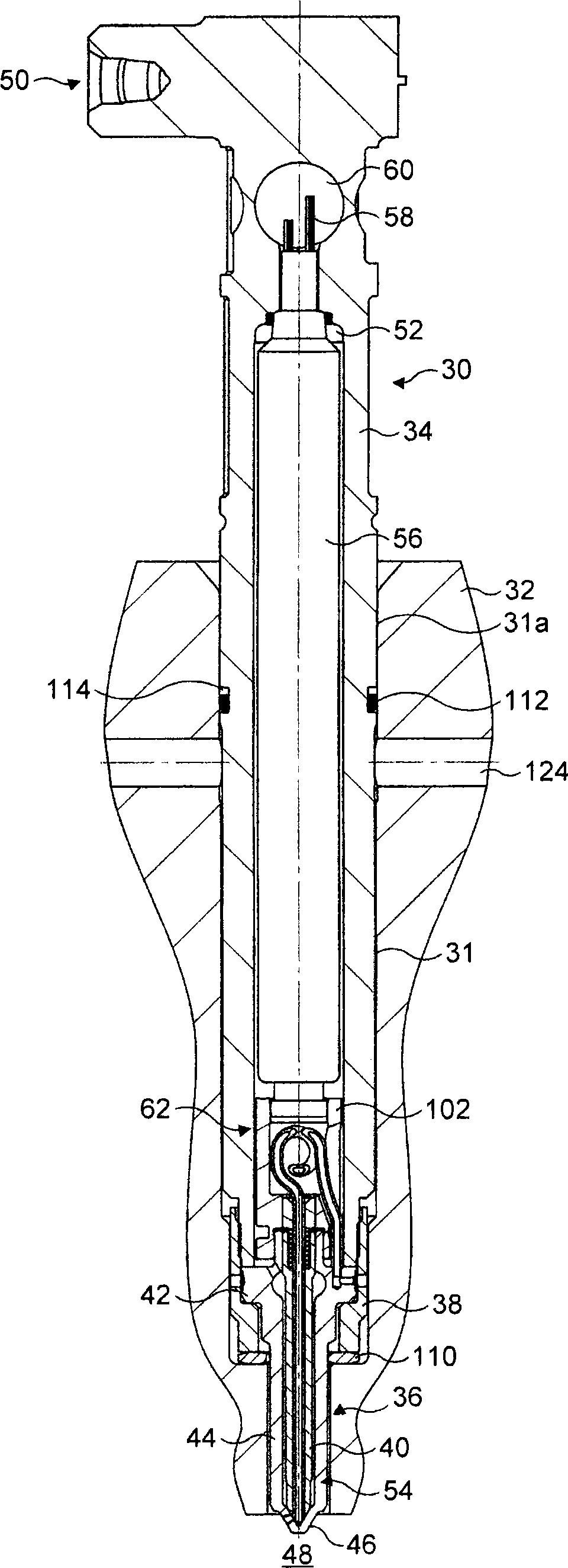
[0101] In all the drawings, the same reference numerals denote the same features, and for clarity, the reference numerals of the features described in other drawings are omitted.

[0102] In the following description, the terms "up" and "down" are used to denote the directions of the fuel injectors shown in the drawings. However, it is understood that the fuel injectors need not be limited to specific directions in use or other aspects. The terms "upstream" and "downstream" are relative to the direction of fuel flow through the injector from the inlet of the injector to the corresponding outlet.

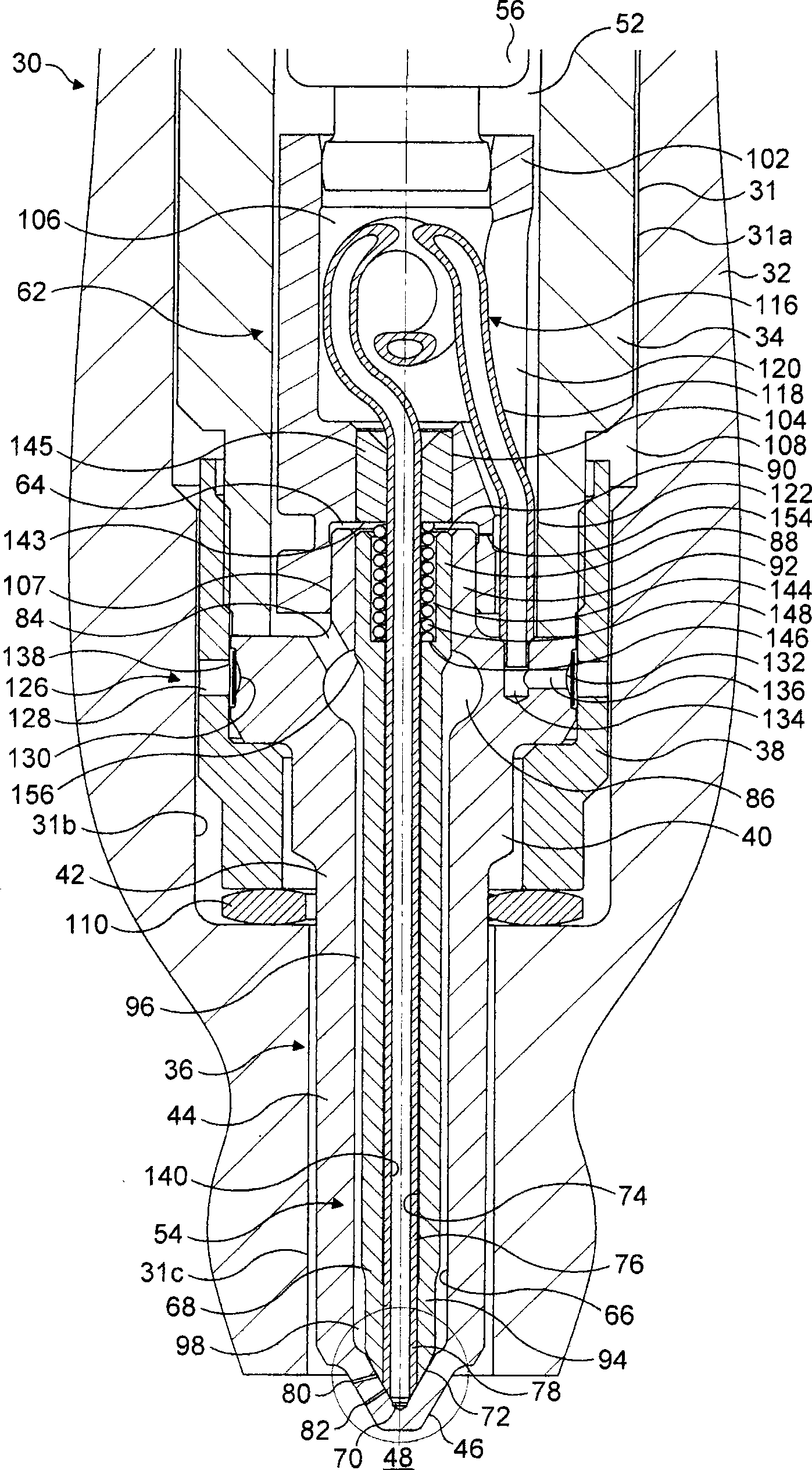
[0103] figure 1 The first embodiment of the fuel injector 30 of the present invention is shown, which is installed in a hole 31 penetrating the cylinder head 32 of an internal combustion engine. The ejector 30 includes an ejector body 34 and an ejector nozzle 36 extending longitudinally.

[0104] The ejector nozzle 36 is fixed to the ejector body 34 by a cap nut 38. Cap nut 38 carries ...


PUM


Abstract

The invention relates to a fuel injector for use in an internal combustion engine, comprising a nozzle body (40) being provided with a nozzle bore (66) and at least one set of one or more outlets for fluid, an outer valve member (68) received within the nozzle bore (66) and being engageable with a first seating region (100a) of the nozzle body (40) to control the flow of a first fluid from a first delivery chamber (98), the outer valve member (68) being provided with an outer valve bore (74), and an inner valve member (76) received within the outer valve bore (74) and being engageable with a second seating region (100b) of the nozzle body (40) to control the flow of a second fluid from a second delivery chamber (142). In various embodiments, the fuel injector can be arranged to allow the first and second fluids to be injected separately and / or together. In one embodiment, the first and second fluids can be mixed within the injector before injection.

Description

Technical field [0001] The invention relates to a fuel injector used in a fuel injection system of an internal combustion engine. More specifically, the present invention relates to a fuel injector in which first and second valve needles are operable to control the injection of two fluids into the combustion space. Background technique [0002] Typically, modern internal combustion engines operate either on the principle of spark ignition or on the principle of compression ignition. In both cases, the reciprocating piston goes through a combustion cycle including intake, compression, work, and exhaust strokes in each cylinder of the engine. During the power stroke, the reciprocating motion of the piston is driven by the rapidly expanding combustion gas in the combustion chamber of the cylinder. [0003] In a spark ignition engine such as a gasoline or petrol engine, the fuel and air mixture, that is, the charge, is introduced into the combustion chamber during the intake stroke. ...

Claims


Application Information

Patent Timeline
Patent Type & Authority Applications(China)
IPC IPC(8): F02M43/04
CPCF02D19/0694F02D19/0642F02D19/061Y02T10/36F02D19/08F02M61/042F02M43/04F02B3/06F02D19/0657F02M2200/46F02M45/086F02B1/12F02M51/0603F02M2200/703F02D19/081F02M2200/21F02M61/182Y02T10/30
Inventor M·P·库科G·格里维斯N·米洛瓦诺维
Owner DELPHI TECH HLDG SARL
Why Eureka
Try Eureka