Fuel injector with divided flowpath nozzle

A fuel injector and flow path technology, applied in fuel injection devices, charging systems, combustion engines, etc., can solve problems such as reduced combustion efficiency, increased emissions, and incomplete combustion

Pending Publication Date: 2021-01-29
FORD GLOBAL TECH LLC
View PDF1 Cites 0 Cited by
  • Summary
  • Abstract
  • Description
  • Claims
  • Application Information

AI Technical Summary

Problems solved by technology

Therefore, during the power stroke, the fuel on the walls may not be completely combusted, increasing emissions (e.g., soot and particulate emissions) and reducing combustion efficiency

Method used


Image

  • Fuel injector with divided flowpath nozzle
  • Fuel injector with divided flowpath nozzle
  • Fuel injector with divided flowpath nozzle

Examples


Embodiment Construction

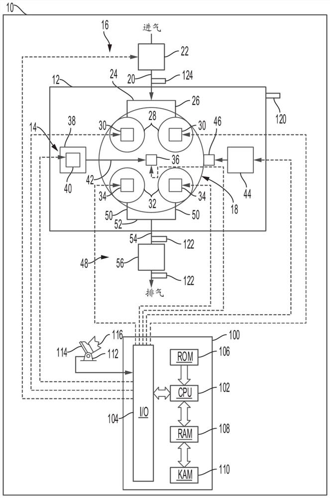
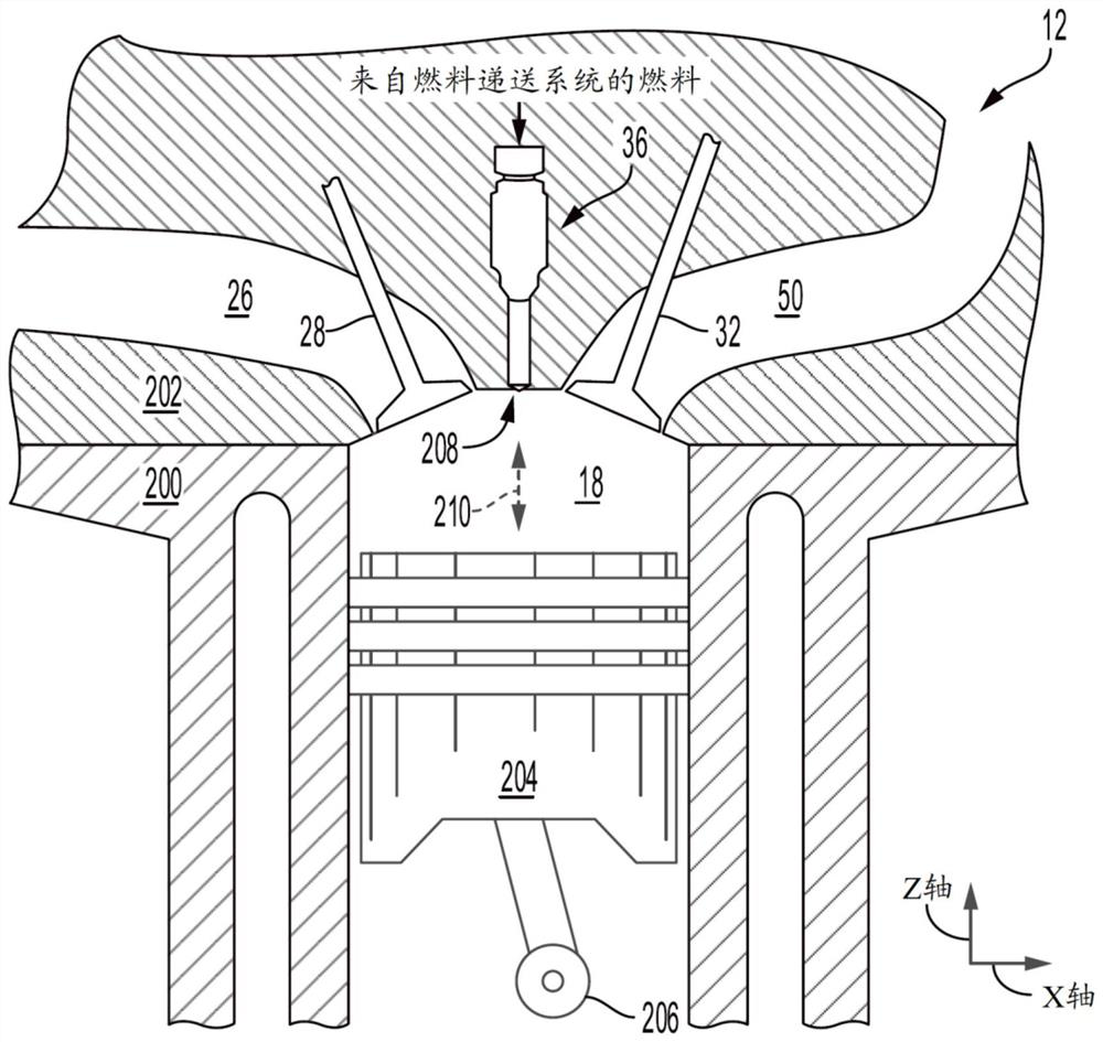
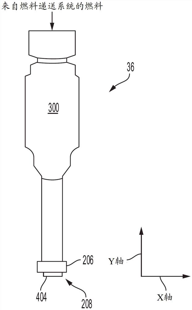
[0025] The following description relates to direct fuel injectors in fuel delivery systems of internal combustion engines. Direct fuel injectors produce a spray pattern that improves fuel atomization and reduces wall wetting. For example, the nozzle may include a divider therein that splits the fuel flow path from the inlet intake side of the nozzle to the outlet exhaust side of the nozzle, thereby providing more outlet orifices for improved fuel distribution and mixing, while Will not compromise the structural integrity of the nozzle.

[0026] Additionally, the internal geometry of the split flow path can be optimized to improve fuel spray characteristics as desired. For example, multiple fuel flow paths may be provided within the nozzle, each fuel flow path being spaced apart from each other and arranged to maximize fuel cavitation through the fuel flow path. Additionally, the cross-sectional shape of the separator, the exit flow path deflection angle, the inlet flow path ...


PUM


Abstract

The invention provides a fuel injector with a divided flowpath nozzle. A fuel delivery system and a direct injector for directly injecting fuel into a cylinder are provided. In one example, a direct fuel injector includes a nozzle in fluidic communication with a fuel source, the nozzle includes at least one fuel flow path that divides into two exit flow paths within the nozzle defining a pluralityof exit orifices stemming from a common inlet orifice thereby improving the atomization and mixing of the fuel as it enters the cylinder. A plurality of spaced-apart divided fuel flow paths may be positioned within the nozzle to further optimize mixing and reduce wall and piston wetting.

Description

technical field [0001] The present specification generally relates to a fuel injector having injection nozzles that divide an inlet flow path into a plurality of outlet flow paths in a fuel delivery system of an engine. Background technique [0002] Fuel delivery systems in internal combustion engines have employed fuel injectors to deliver fuel directly into the engine combustion chamber. Previous direct fuel injectors have included nozzles with a small number of orifices that provide fuel jets to the combustion chamber during desired intervals. One exemplary approach shown by Albrodt in U.S. 9,194,351 is a fuel injection valve. Albrodt discloses a fuel injector having a perforated disc at the end of the injector. The perforated disk includes outlet openings configured to inject fuel in a pattern that promotes mixing. In particular, Albrodt's outlet opening arrangement creates swirls in the fuel spray to increase mixing in the combustion chamber. The inventors have reco...

Claims


Application Information

Patent Timeline
Patent Type & Authority Applications(China)
IPC IPC(8): F02M61/18
CPCF02M61/18F02M61/1853F02B23/101F02B2023/103F02B2075/125F02M61/1806F02M61/1813F02M61/1826F02M61/1833F02M61/184Y02T10/12
Inventor 约瑟夫·F·巴斯马基洪相镇马克·米恩哈特建文·伊
Owner FORD GLOBAL TECH LLC
Why Eureka
Try Eureka