
Hydraulic driving centrifugal liquid cargo pump

A technology of centrifugal fluid and centrifugal pump, applied in the direction of liquid fuel engine, pump, pump device, etc., can solve the problem of easy cross infection between hydraulic oil and goods, and achieve the effect of avoiding cross infection and prolonging service life.

Active Publication Date: 2009-07-22
宁波瑞德森船用泵制造有限公司
View PDF0 Cites 11 Cited by
  • Summary
  • Abstract
  • Description
  • Claims
  • Application Information

AI Technical Summary

Problems solved by technology

[0005] The technical problem to be solved by the present invention is to solve the problem of easy cross-infection between the hydraulic oil and the goods in the hydraulically driven centrifugal liquid cargo pump that is used to transport the chemical medium of the liquid cargo ship

Method used


Image

  • Hydraulic driving centrifugal liquid cargo pump
  • Hydraulic driving centrifugal liquid cargo pump
  • Hydraulic driving centrifugal liquid cargo pump

Examples


Embodiment Construction

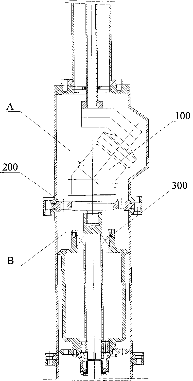
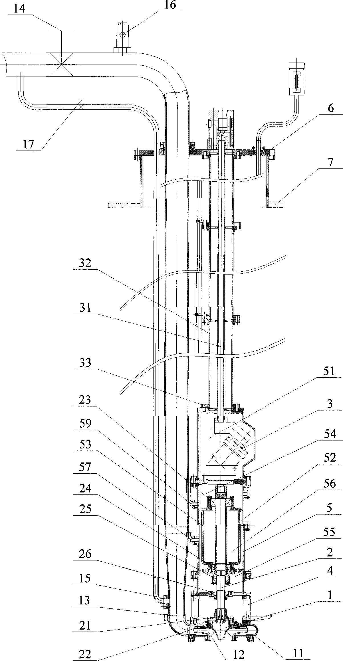
[0025] The present invention provides a hydraulically driven submerged centrifugal liquid cargo pump, which is used for lightening liquid media such as chemicals for liquid cargo ships. The high-pressure oil provided by the hydraulic station is transmitted to the hydraulic motor installed in the centrifugal liquid cargo pump through pipelines. Drive the hydraulic motor to rotate, and the hydraulic motor drives the impeller of the centrifugal liquid cargo pump to rotate to realize the barge transportation of the hydraulic medium.

[0026] The present invention will be described in detail below in conjunction with the accompanying drawings.

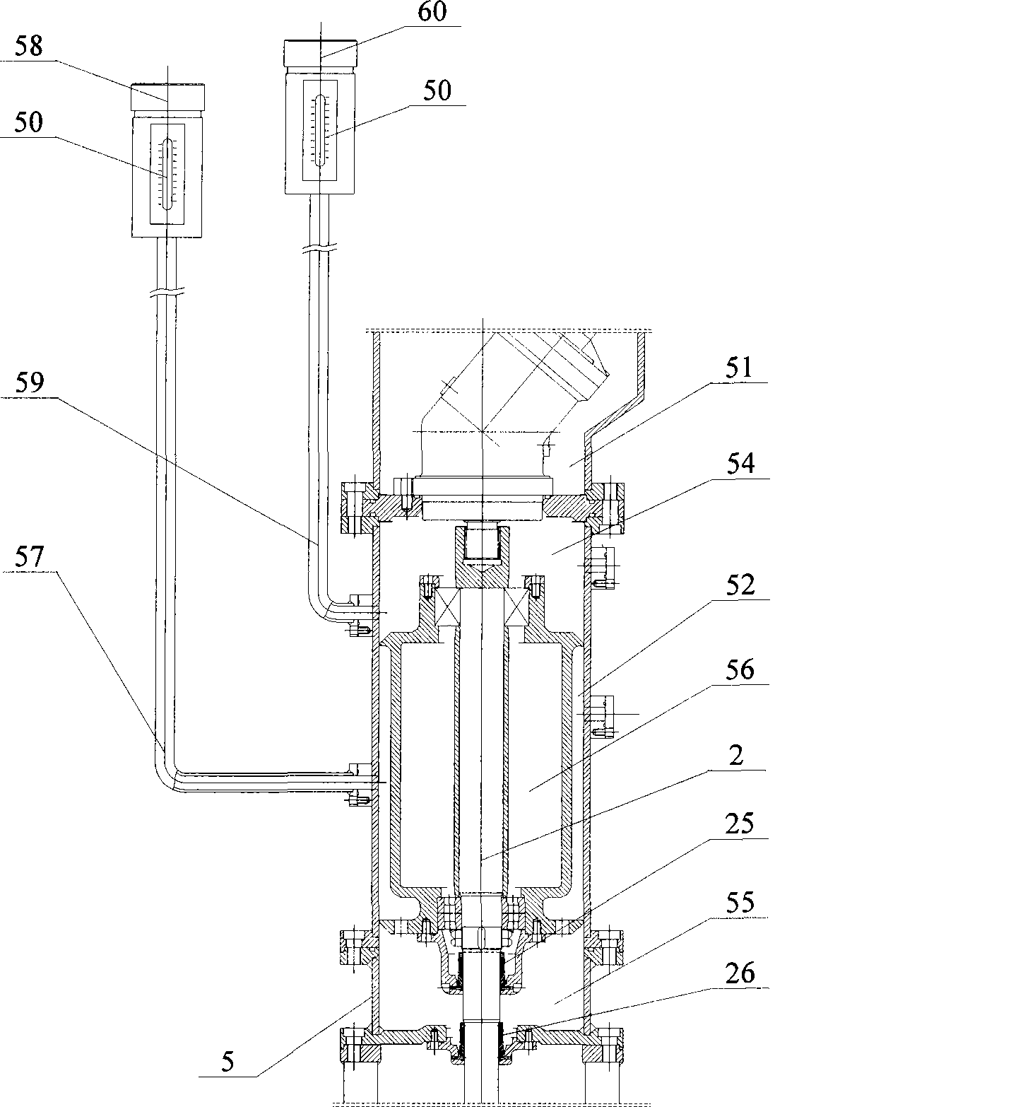
[0027] figure 2 It is a structural schematic diagram of the present invention, such as figure 2 As shown, the present invention includes a centrifugal pump 1, a pump shaft 2, a hydraulic motor 3 and a hydraulic system for driving the hydraulic motor 3 to work.

[0028] The centrifugal pump 1 includes a pump body 11 and an impeller 12 ar...


PUM

PropertyMeasurementUnit
Diameteraaaaaaaaaa

Abstract

The invention discloses a hydraulic drive centrifugal liquid cargo pump used for barging media for a liquid cargo ship. The hydraulic drive centrifugal liquid cargo pump comprises a centrifugal pump, a pump shaft, a hydraulic system of a hydraulic motor and a drive hydraulic motor, a pump body braced frame, a braced frame and a bearing body; the inside of the braced frame is provided with an upper seal cavity and a lower seal cavity, and the hydraulic motor is fixed inside the upper seal cavity; the bearing body is fixedly arranged inside the lower seal cavity and divides the lower seal cavity along the longitudinal direction into a first seal cavity and a second seal cavity, and the bearing body is provided with a bearing body inner cavity and filled with lubricating oil; and an upper bearing and a lower bearing are respectively arranged at the matched place of the pump shaft and the bearing body, and the pump shaft which is arranged inside the second seal cavity is respectively provided with an upper mechanical seal and a lower mechanical seal, as well as the bearing body inner cavity, the second seal cavity and the bottom part of the second seal cavity. In the hydraulic drive centrifugal liquid cargo pump, the hydraulic motor is fixed inside the upper seal cavity which is fully isolated from the first seal cavity, thus avoiding the problem of cross infection of hydraulic oil and goods.

Description

technical field [0001] The invention relates to a pump used for liquid cargo ship lightering medium, in particular to a hydraulically driven centrifugal liquid cargo pump. Background technique [0002] At present, sea transportation is still the most important mode of freight transportation in the world. Tankers refer to transport ships that carry bulk liquid cargo, mainly including oil tankers, liquefied gas tankers and liquid chemical tankers. The liquid cargo pump is used to support the transfer medium of the tanker. [0003] Up to now, the transfer pump used for chemical tankers in China is an electric screw pump, which has the following defects: (1) because the pump is driven by a motor, it cannot transfer flammable and explosive chemicals; (2) because it is not Submersible, so when the depth of the ship's liquid cargo tank exceeds 10 meters, it cannot be pumped, because as we all know, for any equipment, the vacuum degree in the suction pipeline will never reach, let ...

Claims


Application Information

Patent Timeline
IPC IPC(8): F04D13/02F04D29/00F04D29/10F04D29/16F04D29/24F04D29/044
Inventor 赵贵云
Owner 宁波瑞德森船用泵制造有限公司
Learn More