
Highway lighting situation detection method and device

A technology for roads and conditions, which is applied to devices with multiple detectors, measuring devices, and optical devices, etc., can solve the problem that the parameters and status of road lighting devices cannot be clearly specified.

Active Publication Date: 2009-07-22
UST UMWELTSENSORTECHN
View PDF2 Cites 5 Cited by
  • Summary
  • Abstract
  • Description
  • Claims
  • Application Information

AI Technical Summary

Problems solved by technology

However, the disadvantage is that the reflection coefficient ε, which is dependent on the condition of the road surface, influences the results and therefore does not specify the parameters and status of the road lighting installation

Method used


Image

  • Highway lighting situation detection method and device
  • Highway lighting situation detection method and device

Examples


Embodiment Construction

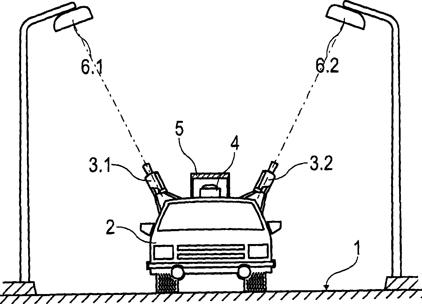
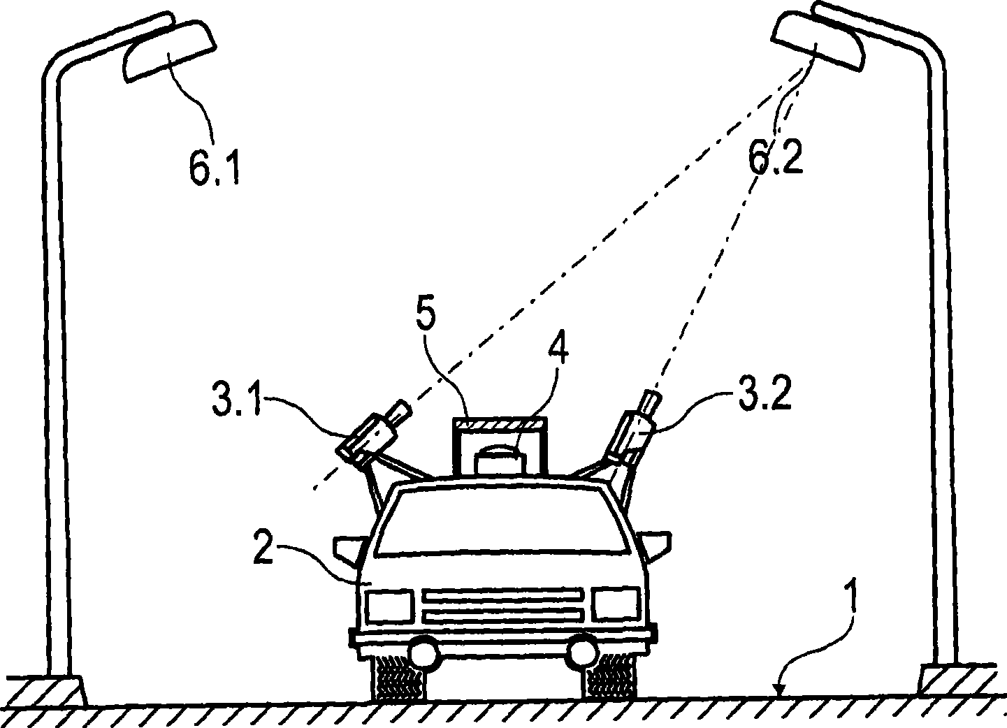
[0025] figure 1 Schematic showing the measurement setup. On the road 1, street lights with luminaires 6 are located on both sides. A camera system comprising two cameras 3 . The cameras 3.1 and 3.2 comprise photosensitive sensors and are oriented in the direction of the luminaire 6, wherein the first camera 3.1 detects the luminaire 6.1 on one side of the roadway assigned to it, and the second camera 3.2 detects the luminaire on the other side of the road. Illuminators 6.2. The cameras 3.1 and 3.2 operate in the saturation region in order to determine the shape of the illuminator by analyzing the contour edges. The type of illuminators and their number can thus be determined.

[0026] The device is arranged in a housing which is detachably connected to the motor vehicle 2 . A sensor 4 is located behind the specially light-transmitting plate 5 , with which sensor 4 the light intensity or illuminance of the illuminant 6 can be detected. The plate 5 is matched to the applic...


PUM


Abstract

The invention relates to a method and a device which are used for detecting highway lighting condition. The invention aims at providing a method and a device so as to illustrate the condition of carriageway lighting device. The illustration is unrelated to disturbing influence as possible, and can be detected under the unobstructed traffic. According to the invention, a method is utilized to realize the aim, wherein the optical density is measured at the back of a plate which specially determines light transmission with regard to spectral transmissivity and absolute ttransmissivity, and the optical intensity of a luminous body (6) is also detected.

Description

technical field [0001] The invention relates to a method and a device for detecting the lighting situation of a road. [0002] The invention can be used in particular for selective lighting measurements of roads and makes it possible to check the lighting conditions as well as the efficacy and effectiveness of road lighting. Background technique [0003] In order to evaluate the illumination of the roadway, it is known to measure the illumination density present on the roadway in order to obtain information on the visibility conditions for road users. [0004] Various methods and arrangements are known in the prior art for determining the lighting conditions on a roadway. [0005] DE 23 55 033 A1 discloses a light receiver (Lichtempfaenger) which detects and evaluates changes relative to a stored basic brightness (Grundhelligkeit). Thus, for example time and speed measurements as well as optional lighting measurements are possible. The light receiver comprises a direction...

Claims


Application Information

Patent Timeline
Patent Type & Authority Applications(China)
IPC IPC(8): G01J1/00G01B11/24G01S5/02
CPCG01J1/02G01J1/0219G01J1/4228
Inventor O·吉斯维特C·卢斯宋梦华张强乐跃雄
Owner UST UMWELTSENSORTECHN
Learn More