
Solid light source, projecting system and bundling lighting fixture employing the device

A solid-state light source and solid-state light-emitting technology, which is applied to the components of lighting devices, light sources, projection devices, etc., can solve the problems of reduced light export efficiency, increased light output of light sources, and difficulty in achieving light output, so as to reduce light loss and improve The effect of light production and size increase

Inactive Publication Date: 2009-07-29
SHENZHEN HIGHMIGHT TECH
View PDF1 Cites 8 Cited by
  • Summary
  • Abstract
  • Description
  • Claims
  • Application Information

AI Technical Summary

Problems solved by technology

However, there is a serious defect in the technical solution disclosed in this patent: the LED chip arranged in the rod-shaped optical member is not only the source of providing the light output of the light source, but also guides the emitted light from the inside of the rod-shaped optical member to the light-emitting end surface obstacles, because when the light emitted by the LED chip is repeatedly reflected and exported by the reflective surface inside the rod-shaped member, once the light hits the LED chip, it will be absorbed by the LED chip and repeatedly reflected and attenuated inside the chip, becoming chip heat loss
Therefore, in order to obtain more light output, more LED chips are arranged inside the rod-shaped member, but at the same time, more obstacles are set for the derivation of light, which reduces the efficiency of light derivation. The purpose of increasing the number of LEDs to greatly increase the light output of the light source
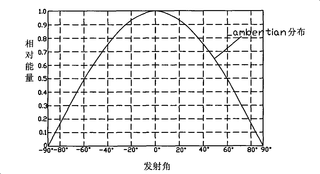
In addition, if figure 2 As shown, the luminous characteristics of the LED chip satisfy the "Lambertian distribution". Since the luminous energy of the LED chip is related to its emission angle, the smaller the emission angle, the greater the emission energy, and the larger the emission angle, the smaller the emission energy. In the technical solution disclosed in the above-mentioned patent, the smaller the emission angle of the light, the more reflections it will experience inside the rod-shaped member, and the greater the probability of it being absorbed by the LED chip and lost
The final result is that when a large number of LED chips are arranged inside the rod-shaped member in order to seek high light output, only light with a small energy and a large emission angle can be more effectively exported from the light-emitting end surface, and the light export efficiency is very low. It is difficult to achieve the purpose of greatly increasing light production

Method used


Image

  • Solid light source, projecting system and bundling lighting fixture employing the device
  • Solid light source, projecting system and bundling lighting fixture employing the device
  • Solid light source, projecting system and bundling lighting fixture employing the device

Examples


Embodiment 1

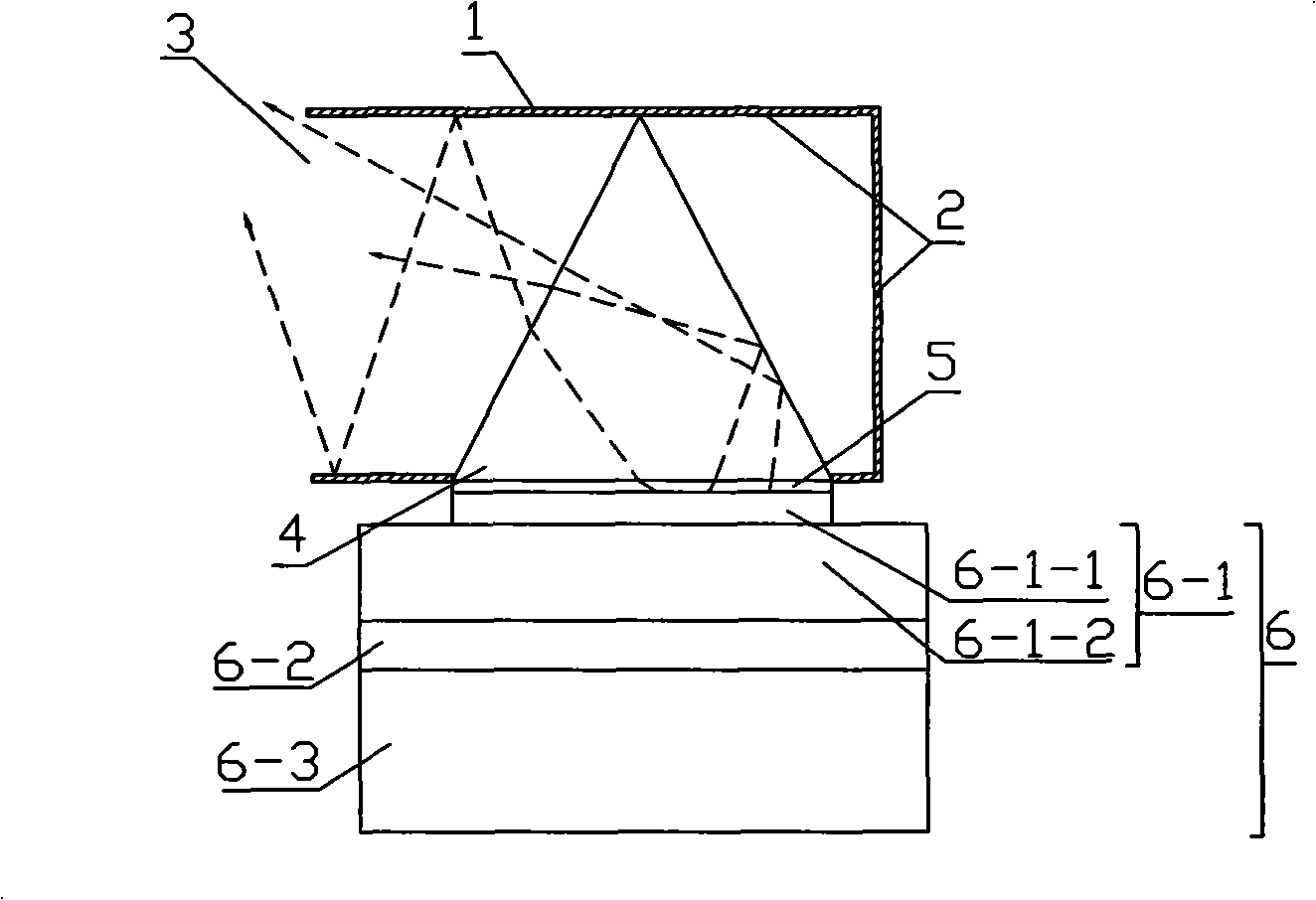
[0058] Example 1, such as image 3 As shown, a solid-state light source device includes a hollow hexahedron optical component 1, and its front wall is provided with a light outlet 3, the size of the light outlet 3 matches the projection optical system, and a light inlet is provided on the inner wall of one side of the hexahedron optical component 1. 5. A specular reflective layer 2 is provided on the inner wall surface of the optical member 1 except for the light outlet 3 and the light inlet 5, and a light guide prism 4 can be installed at the light inlet 5, as long as the sum of the bottom surface of the light guide prism 4 is equal to the light inlet 5 Matching, it is also possible to set a light guide prism array plate composed of multiple light guide prisms of different sizes in parallel without gaps. Component 6, the solid-state light-emitting component includes a light-emitting board 6-1, and the light-emitting board 6-1 is composed of a heat sink 6-1-2, a light-emitting...

Embodiment 2

[0059] Example 2, such as Figure 4a As shown, a solid-state light source device includes a hollow hexahedron optical component 1, the front wall of which is provided with a light outlet 3, the size of the light outlet 3 matches the projection optical system, and four sides of the hexahedron optical component 1 are respectively provided with four inner walls. The light entrance 5, except for the light exit 3 and the light entrance 5, the inner wall surface of the optical member 1 is provided with a specular reflection layer 2, and six light guide prisms are parallel without gaps to form a light guide prism array plate 4, which is arranged on the light entrance 5 , the light guide prism array plate 4 can also be made up of other different numbers of light guide prisms, the number of light guide prisms is related to its size, the setting of adjacent side light guide prism array plates, and the light guide prisms are symmetrical strip wedge-shaped prisms , the bottom surface of t...

Embodiment 3

[0063] Example 3, such as Figure 5a As shown, a solid-state light source device includes a hollow hexahedron optical component 1, the front wall of which is provided with a light outlet 3, the size of the light outlet 3 matches the projection optical system, and four sides of the hexahedron optical component 1 are respectively provided with four inner walls. The light entrance 5, except for the light exit 3 and the light entrance 5, the inner wall surface of the optical member 1 is provided with a specular reflection layer 2, and six light guide prisms are parallel without gaps to form a light guide prism array plate 4, which is arranged on the light entrance 5 , the light guide prism array plate 4 can also be made up of other different numbers of light guide prisms, the number of light guide prisms is related to its size, the setting of adjacent side light guide prism array plates, and the light guide prisms are symmetrical strip wedge-shaped prisms , the bottom surface of t...


PUM


Abstract

The invention discloses a solid state light source device, a projection system and a gathering illumination lamp adopting the device. The solid state light source comprises a hollow optical component. Air, vacuum or other light transmission media are included in the cavity of the optical component, a light-emitting window is arranged on the optical component in polyhedron shape; at least a light-entering window is arranged on the optical component, at least a light conducting prism is arranged corresponding to the light-entering window, a solid state luminescence component is arranged corresponding to the bottom side of the light conducting prism, reflection parts are positioned in the optical component or both in and out of the optical component, the light sent out by the solid state luminescence component is refracted or totally reflected by the light conducting prism, reflected by the reflection parts or directly emitted from the light-emitting window of the optical component. By fully utilizing the side wall of the optical component to be equipped with more solid state luminescence components, the device is capable of enlarging the effective light-emitting area of the solid state luminescence components, increasing the light output of light source under the condition of maintaining the same light-emitting window area; and all the light sent out by a plurality of solid state luminescence components is put together and educed toward the direction of the light-emitting window through the reflection part and the light conducting prism, which not only increases the light output but also educes light efficiently.

Description

technical field [0001] The invention relates to a light source device and its application, in particular to a solid-state light source device, a projection system using the device, and a clustered lighting fixture. Background technique [0002] As a new type of high-brightness, long-life light source, solid-state light-emitting devices such as high-power LEDs (including OLEDs) have achieved considerable development in lighting and other application fields. The lack of projection light sources, but to apply LED and other solid-state light-emitting devices to projection systems, it is necessary to require the constituted light source to be an ideal point light source, but the illuminant of each LED is a semiconductor chip with a certain light-emitting area. It is essentially a small surface light source, and because the luminance of a single LED chip is limited, in order to achieve a large enough luminous flux, it is usually necessary to arrange multiple LED chips in an array,...

Claims


Application Information

Patent Timeline
Patent Type & Authority Applications(China)
IPC IPC(8): F21V5/02G03B21/20F21Y101/02F21Y115/10
Inventor 曹嘉灿
Owner SHENZHEN HIGHMIGHT TECH
Learn More