Method for identifying multiple true touch point by infrared touch screen
An infrared touch screen and real touch technology, applied in the input/output process of data processing, instruments, electrical digital data processing, etc., can solve the problems of multi-point identification blind spots, small emission angles, low resolution, etc., and achieve improved infrared scanning Increased speed, responsiveness, and improved accuracy
- Summary
- Abstract
- Description
- Claims
- Application Information
AI Technical Summary
Problems solved by technology
Method used
Image
Examples
Embodiment 1
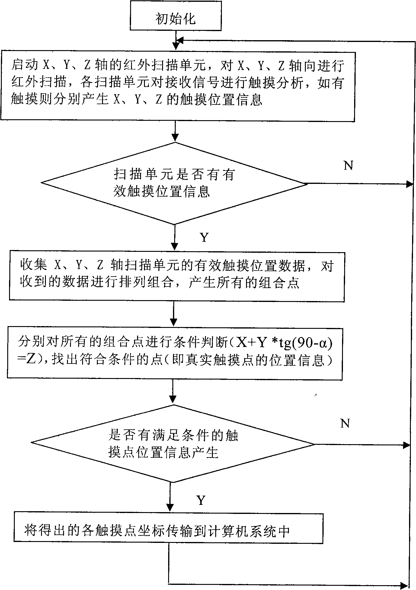
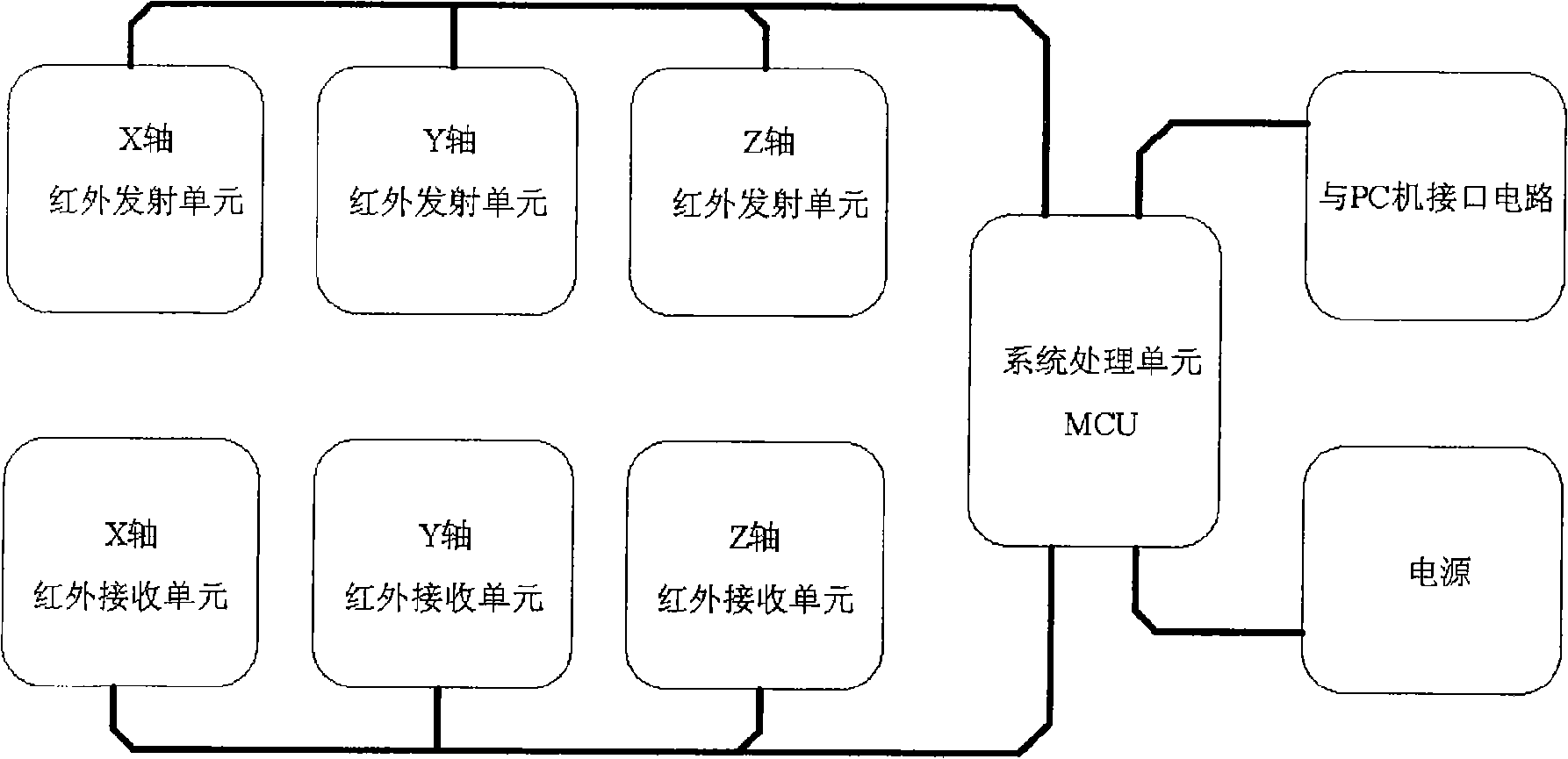
[0039] A method for identifying a plurality of real touch points on an infrared touch screen, comprising the steps of: a, setting a Z-axis infrared scanning component on an X-axis infrared scanning component and a Y-axis infrared scanning component of the infrared touch screen; b, starting the infrared touch screen, driving The infrared emitting unit and the infrared receiving unit of the X-axis, Y-axis and Z-axis infrared scanning components perform infrared scanning on the X-axis, Y-axis and Z-axis directions, the infrared emitting unit sends the touch signal to the infrared receiving unit, and the infrared receiving unit Perform touch analysis on the received touch signal to generate touch position information on the X-axis, Y-axis and Z-axis; c. The controller judges whether the generated touch position information is valid touch position information. If there is no valid touch position information, return to initialization. When valid touch position information, the contro...
Embodiment 2
[0067] A method for identifying a plurality of real touch points on an infrared touch screen, comprising the steps of: a, setting a Z-axis infrared scanning component on an X-axis infrared scanning component and a Y-axis infrared scanning component of the infrared touch screen; b, starting the infrared touch screen, driving The infrared emitting unit and the infrared receiving unit of the X-axis, Y-axis and Z-axis infrared scanning components perform infrared scanning on the X-axis, Y-axis and Z-axis directions, the infrared emitting unit sends the touch signal to the infrared receiving unit, and the infrared receiving unit Perform touch analysis on the received touch signal to generate touch position information on the X-axis, Y-axis and Z-axis; c. The controller judges whether the generated touch position information is valid touch position information. If there is no valid touch position information, return to initialization. When valid touch position information, the contro...
Embodiment 3
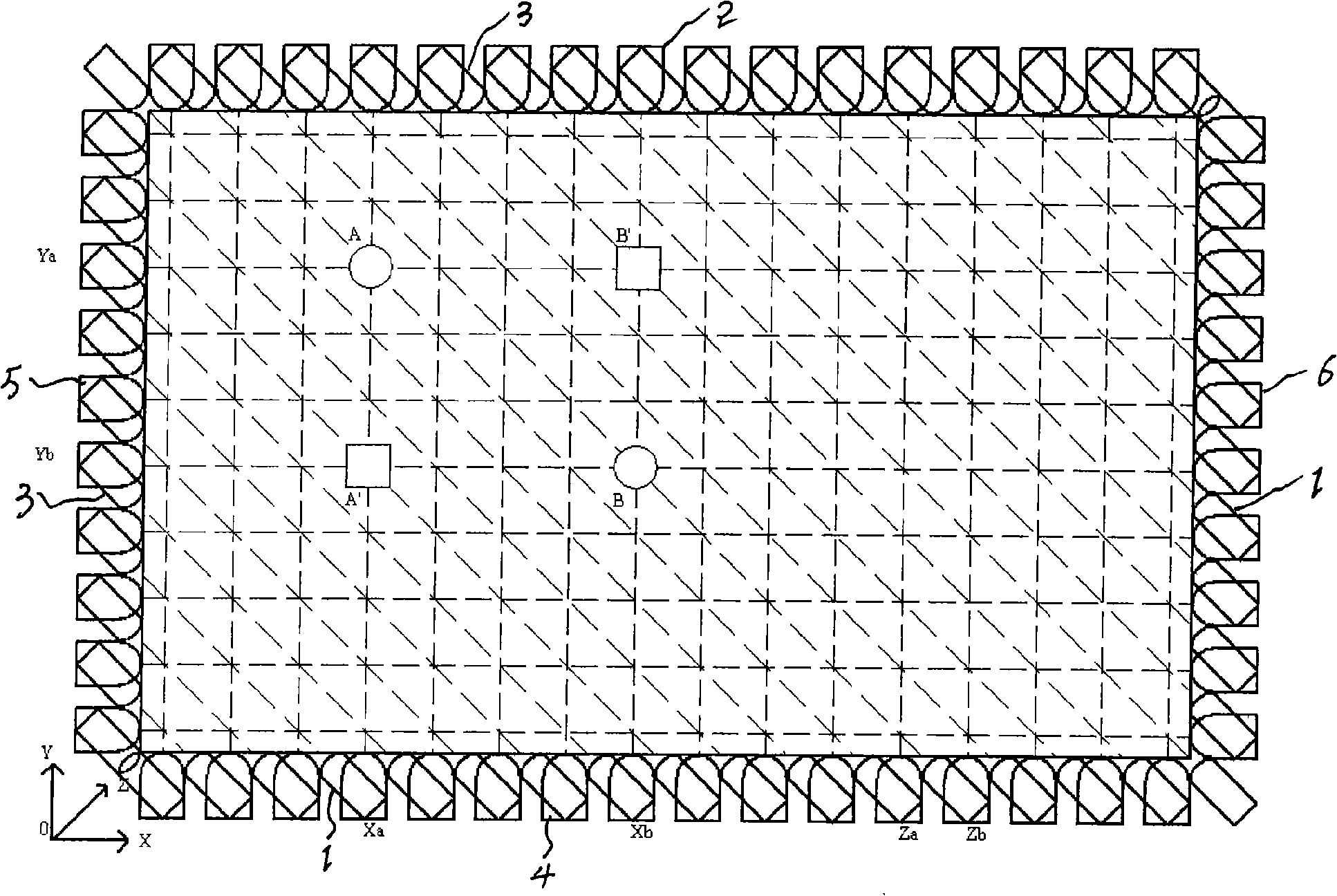
[0072] The best implementation mode of the present invention is α=45°, and the following takes the two-point touch of α=45° as an example to expand the description:
[0073] The present invention includes infrared scanning components in three directions of X / Y / Z, and one touch point A will generate three coordinate values of Xa, Ya and Za. Since the included angle between the Z axis and the X / Y axis is 45 degrees, Xa, Ya, and Za satisfy the relationship of Za=Xa+Ya. If it is a two-point touch, six coordinate values Xa, Ya, Za, Xb, Yb, and Zb will be generated, and the following eight coordinate combinations may be formed:
[0074] A: (Xa, Ya, Za)
[0075] B: (Xa, Yb, Za)
[0076] C: (Xb, Ya, Za)
[0077] D: (Xb, Yb, Za)
[0078] E: (Xa, Ya, Zb)
[0079] F: (Xa, Yb, Zb)
[0080] G: (Xb, Ya, Zb)
[0081] H: (Xb, Yb, Zb)
[0082] Substitute the coordinates of the above eight points into the conditional relational formula: X+Y=Z, only A and H meet the conditions, so th...
PUM
 Abstract
Description
Claims
Application Information
 - R&D
- Intellectual Property
- Life Sciences
- Materials
- Tech Scout
- Unparalleled Data Quality
- Higher Quality Content
- 60% Fewer Hallucinations
Browse by: Latest US Patents, China's latest patents, Technical Efficacy Thesaurus, Application Domain, Technology Topic, Popular Technical Reports.
© 2025 PatSnap. All rights reserved.Legal|Privacy policy|Modern Slavery Act Transparency Statement|Sitemap|About US| Contact US: help@patsnap.com


