Tension bracing mechanism and tension bracing method thereof of template clamp tool

A template clamp and fixture technology, applied in clamping, manufacturing tools, metal processing machinery parts, etc., can solve the problems of reducing production quality, increasing processing costs, processing failure, etc., to reduce processing failure rate, improve product quality and Production efficiency, the effect of saving processing costs

Inactive Publication Date: 2009-08-05
SHENZHEN MUSEN TECH
0 Cites 9 Cited by

AI-Extracted Technical Summary

Problems solved by technology

When the cutting process is completed, after the finished product is disassembled, the tension force on both sides of the formwork disappears, and the formwork shrinks inwardly, resulting in abnormal movement of the cut holes on the fini...

Method used

The embodiment of the present invention is by adding a brace control device in the template clamp fixture brace mechanism, and by setting the limit brace strength to the brace control device, the maximum brace tension of the template workpiece is controlled, and then the product is improved. Improve quality an...

Abstract

The invention discloses a template jig tensioning mechanism, which comprises a substrate with a guide rail, a screw mandrel arranged on the substrate and provided with a transmission nut, and a holding jaw jig fixed on the transmission nut, wherein the holding jaw jig is fixedly connected with a sliding block arranged on the guide rail; the screw mandrel is provided with transmission threads; and the mechanism also comprises a power unit and a tensioning control device connected between the power unit and one end of the screw mandrel. The invention also provides a template jig tensioning method. The template jig tensioning mechanism controls the maximum tensioning strain of a template workpiece through arrangement of the tensioning control device and setting of limit tensioning force for the tensioning control device to improve product quality and production efficiency, reduce processing failure rate and effectively save processing cost.

Application Domain

Technology Topic

Image

  • Tension bracing mechanism and tension bracing method thereof of template clamp tool
  • Tension bracing mechanism and tension bracing method thereof of template clamp tool
  • Tension bracing mechanism and tension bracing method thereof of template clamp tool

Examples

  • Experimental program(1)

Example Embodiment

[0014] The preferred embodiments of the present invention will be described below with reference to the drawings.
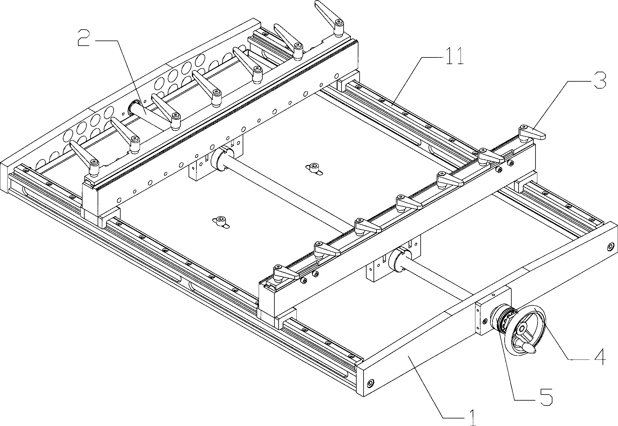
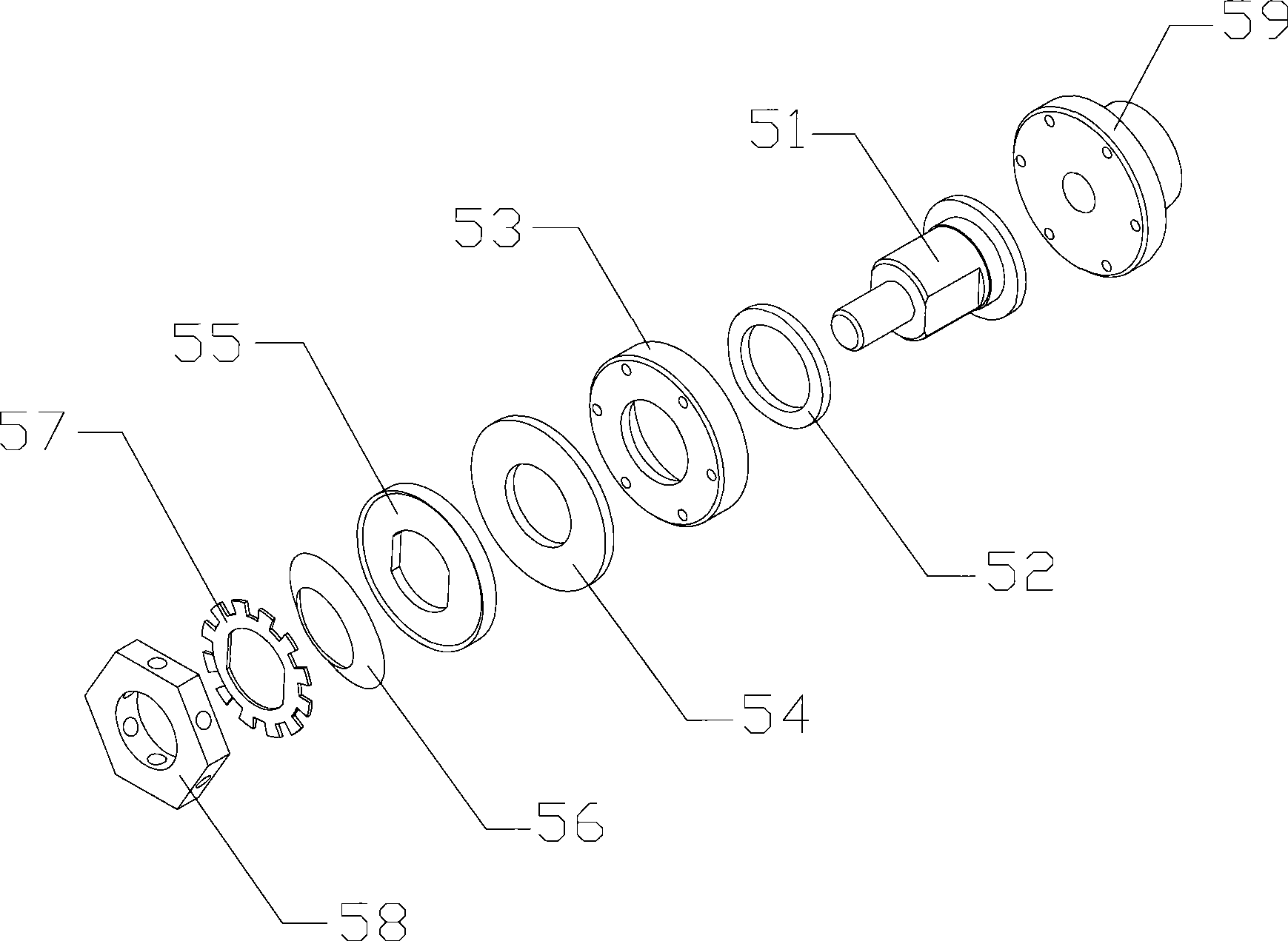
[0015] Refer to figure 1 As shown, the template clamping fixture stretching mechanism of the embodiment of the present invention includes a base 1 provided with a guide rail 11. A screw rod 2 with a drive nut is installed on the base 1, and a clamping jaw clamp 3 and a clamping jaw clamp 3 are fixed on the transmission nut. It is also fixedly connected to the sliding block installed on the guide rail 11. The screw rod 2 is bounded by the center, and the two ends are respectively provided with transmission threads with opposite spiral directions. It also includes a power device and a tension control device 5. In the embodiment of the present invention, the power The device adopts a rocking handle 4, which is fixed to one end of the tension control device 5 through a threaded connection, and the other end of the tension control device 5 and the screw rod 2 are fixed together through a threaded connection. Further, the stretching control device 5 includes a shaft base 51, a fixed nut 58, a fixing base 59, and a copper ring 52, a base 53, a copper washer 54, and a bearing that are in close contact with each other and sleeved on the shaft base 51 in sequence. The disc 55, the disc spring 56, the sun ring washer 57, and the fixing nut 58 are in close contact with the sun ring washer 57, and are fixed on the shaft base 51 through a screw connection. One end of the fixing seat 59 is fixed with the base 53 by bolt connection, and the other end is connected with one end of the screw rod 2 by a screw connection to form a whole body.
[0016] In the specific implementation, first use a wrench to adjust the tightness of the fixed nut 58 to set the maximum tensile force of the equipment on the template workpiece. During the process of adjusting the fixed nut 58 to compress the sun ring gasket 57, the sun ring gasket 57 bends inward under pressure, so as to better closely contact with the disc spring 56. The disc spring 56 is compressed and deformed, which also generates a certain pressure on the bearing plate 55. The bearing plate 55 is passed through a copper gasket 54 The friction force is generated on the base 53. Due to the transmission of pressure, the shaft seat 51 also generates friction on the base 53 through the copper ring 52; then rotate the rocker 4, when the torque generated by it is less than that of the copper washer 54 and the copper ring 52 on the base The friction force of 53 will drive the shaft base 51 and the fixed base 59 to rotate, and then drive the screw 2 to rotate. Because the screw 2 is bounded by the center, the two ends are respectively provided with transmission threads with opposite spiral directions, so it is installed in the wire The two drive nuts on the rod 2 will move in relative directions, and then drive the clamping jaw clamp 3 fixed on the nut to make corresponding opening and closing movements along the guide rail 11. At this time, the clamping jaw clamp 3 can stretch or loosen the template workpiece When the torsion force generated is greater than the frictional force of the copper washer 54 and the copper ring 52 on the base 53, the bearing plate 55 will be idling due to slipping, so that the base 53 and the fixed seat 59 cannot be rotated by the friction force, and the screw 2 is also If it cannot follow the rotation, the gripper clamp 3 also stands still.
[0017] The present invention also provides a method for pulling and supporting a template clamp fixture, please refer to image 3 As shown, the specific process is as follows:
[0018] Step S1 presets the ultimate pulling force;
[0019] Step S2: The template clamp fixture pulls the template workpiece according to the ultimate tension force.
[0020] Step S2 further includes the following steps:
[0021] When the template workpiece is not stretched and flattened, if the screw is rotated, the template clamp fixture will continue to support the template workpiece;
[0022] When the template workpiece is stretched and flattened, if you continue to rotate the screw, the template clamp fixture will slip and stop pulling the template workpiece.
[0023] In the specific implementation, the tightness of the fixing nut 58 is adjusted first, and the fixing nut 58 presses the sun ring gasket 57 so that it bends inward and tightly abuts on the disc spring 56. The disc spring 56 is also compressed and compressed. It deforms and generates a certain pressure on the bearing plate 55. Similarly, due to the transmission of pressure, the bearing plate 55 generates friction force on the base 53 through the copper gasket 54, and the shaft base 51 also generates friction force on the base 53 through the copper ring 52. Thereby setting the ultimate pulling force of the template clamping fixture to the template workpiece; then turning the crank 4, when the torque generated by it is less than the friction force of the copper washer 54 and the copper ring 52 on the base 53, it will drive the shaft seat 51 and the fixed seat 59 rotate, and then drive the screw 2 to rotate, so that the template clamp fixture continues to stretch the template workpiece; when the torque generated by it is greater than the friction force of the copper washer 54 and the copper ring 52 on the base 53, the bearing plate 55 It will be idling due to slipping, so that the base 53 and the fixed seat 59 cannot be rotated by the friction force, and the screw 2 cannot follow the rotation, so the template clamp fixture stops pulling the template workpiece
[0024] In the embodiment of the present invention, a bracing control device is added to the template clamp and jig bracing mechanism, and a limit bracing force is set for the bracing control device to control the maximum bracing tension of the template workpiece, thereby improving product quality and production Efficiency, reduce the processing failure rate, and effectively save processing costs. The template workpiece in the embodiment of the present invention mainly includes a metal template (such as a steel sheet template, a nickel sheet template, a copper sheet template, etc.) or a plastic template.
[0025] The above are only the preferred embodiments of the present invention. Of course, the power plant can also use a drive motor to provide the power source. It should be pointed out that for those of ordinary skill in the art, without departing from the principle of the present invention, Several improvements and modifications can also be made, and these improvements and modifications should also be regarded as the protection scope of the present invention.

PUM

no PUM

Description & Claims & Application Information

We can also present the details of the Description, Claims and Application information to help users get a comprehensive understanding of the technical details of the patent, such as background art, summary of invention, brief description of drawings, description of embodiments, and other original content. On the other hand, users can also determine the specific scope of protection of the technology through the list of claims; as well as understand the changes in the life cycle of the technology with the presentation of the patent timeline. Login to view more.

Similar technology patents

Classification and recommendation of technical efficacy words

Why Eureka
Try Eureka