Reverse-installation posture assembling positioning tool for side beam welding

A technology for positioning tooling and side beams, which is applied in welding equipment, auxiliary welding equipment, welding/cutting auxiliary equipment, etc., can solve the problem that the axle hinge seat welding posture and position are prone to deviation, the positioning of the axle hinge seat and the welding process are time-consuming and laborious, Welding quality is difficult to be effectively controlled and other problems, to achieve the effect of improving production efficiency and product quality, simple and practical structure, and easy to popularize

Active Publication Date: 2018-12-21
CRRC CHANGCHUN RAILWAY VEHICLES CO LTD
View PDF10 Cites 4 Cited by
  • Summary
  • Abstract
  • Description
  • Claims
  • Application Information

AI Technical Summary

Problems solved by technology

[0008] In order to solve the existing welding and positioning method of the axle hinge seat and spring seat based on the normal posture of the side beam, it will be affected by its own gravity, which will affect the positioning accuracy and welding quality of the arc plate group at the welding interface, and because of the load-bearing beam structure of the side beam The curve or curved surface of the lower cover plate of the side sill has a special structure. After welding, the welding deformation of the arc curve section B is relatively large and the symmetry is poor. As a result, the positioning and welding process of the two sets of axle hinge seats is time-consuming and laborious, requiring a lot of work. Surveying and marking and post-welding repair operations, and, under the deformation after welding and cooling, the welding posture and position of the axle hinge seat are prone to deviations, which are difficult to maintain, resulting in the technical problem that the welding quality is difficult to be effectively controlled. The invention provides a reverse posture assembly and positioning tool for side beam welding

Method used


Image

  • Reverse-installation posture assembling positioning tool for side beam welding
  • Reverse-installation posture assembling positioning tool for side beam welding
  • Reverse-installation posture assembling positioning tool for side beam welding

Examples


Embodiment Construction

[0050] The present invention will be described in further detail below in conjunction with the accompanying drawings.

[0051] Such as Figure 9 with Figure 10 As shown, the anti-installation posture assembly positioning tool for side beam welding of the present invention includes a foundation platform 2, a positioning seat 3 for the middle section of the side beam, two spring seat pressing mechanisms 4 and two axle hinge seat door arch positioners 5 , the lower ends of the positioning seat 3 of the middle section of the side beam, the two spring seat pressing mechanisms 4 and the lower ends of the two axle hinge seat door arch positioners 5 are all fixedly connected to the end surface of the foundation platform 2, and the positioning seat 3 of the middle section of the side beam is located on the foundation platform 2 In the center of the center, two spring seat pressing mechanisms 4 are symmetrically arranged on the left and right sides of the positioning seat 3 in the mid...


PUM


Abstract

The invention discloses a reverse-installation posture assembling positioning tool for side beam welding, and belongs to the field of auxiliary clamping devices for welding assembling positioning of railway vehicle bogie side beam devices. The reverse-installation posture assembling positioning tool comprises a foundation platform, a side beam middle section positioning seat, two spring seat pressing mechanisms and two axle hinge seat door arch positioners, the lower end of the side beam middle section positioning seat, the lower ends of the two spring seat pressing mechanisms and the lower ends of the two axle hinge seat door arch positioners are fixedly connected to the end surface of the foundation platform, the side beam middle section positioning seat is located in the center of the foundation platform, the two spring seat pressing mechanisms are symmetrically arranged on the left side and the right side of the side beam middle section positioning seat, and the two axle hinge seatdoor arch positioners are symmetrically and fixedly connected to the two ends of the foundation platform. According to the reverse-installation posture assembling positioning tool, the mapping and marking operation performed during side beam assembling can be completely avoided, the mode of the reverse-installation posture assembling positioning tool for positioning components is simple, convenient, fast, accurate and reliable, moreover, welding deformation of all portions on a pinion-shaped side beam can be effectively inhibited, the adjusting and repairing work after welding is reduced, andtherefore, the production efficiency and the product quality can be greatly improved.

Description

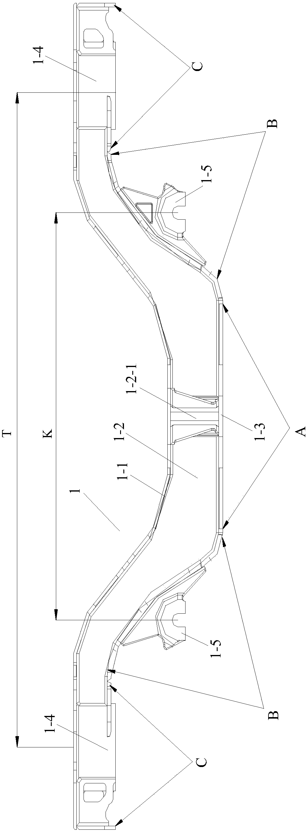
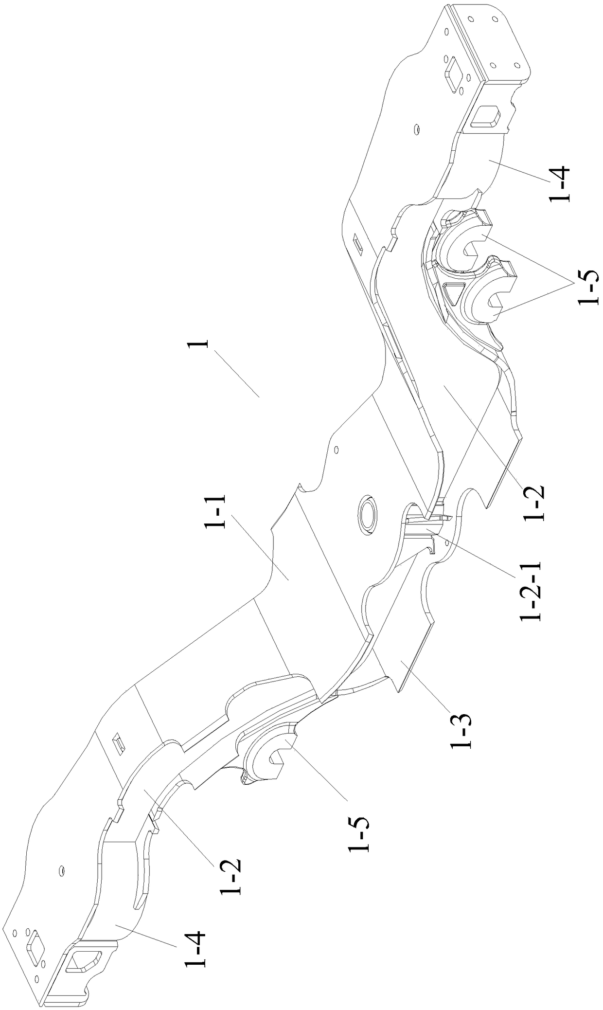
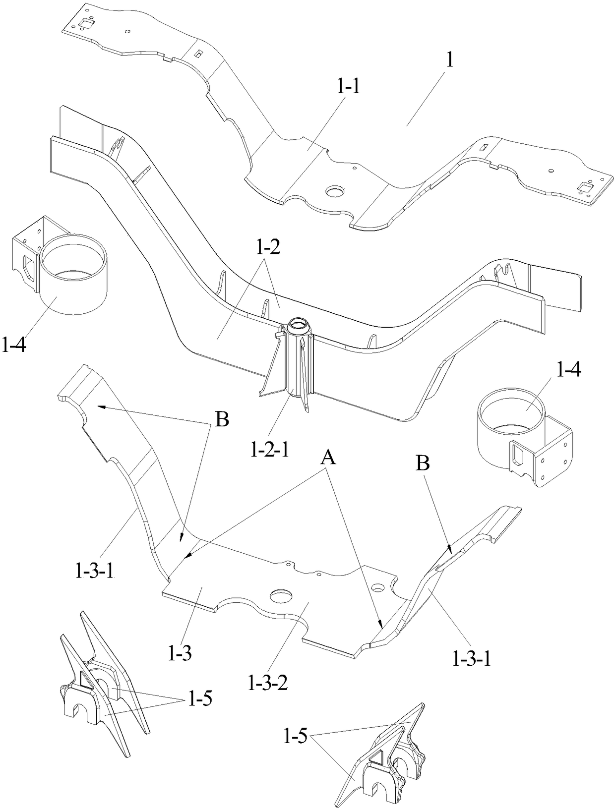
technical field [0001] The invention belongs to the field of auxiliary clamping devices for welding group pair positioning of rail vehicle bogie side beam devices, and in particular relates to a reverse posture group pair positioning tool for side beam welding. Background technique [0002] Such as Figure 1 to Figure 3 As shown, the main part of the side beam 1 on the rail passenger car bogie frame is a joint welded by the side wall double splint 1-2, the side beam upper cover plate 1-1, and the side beam lower cover plate 1-3. The load-bearing beam structure is formed, and the overall shape of the load-bearing beam structure is similar to the middle section of the torso and the wings of a bird with two wings spread out. A symmetrical and upturned arc curve segment B and two symmetrical upper horizontal ends C. The shape of the upper and lower edge contour lines of the side wall double splint 1-2 and the curved surface shape of the side beam upper cover plate 1-1 are corre...

Claims


Application Information

Patent Timeline
Patent Type & Authority Applications(China)
IPC IPC(8): B23K37/04
CPCB23K37/0443B23K37/0461
Inventor 李靓怡王子栋李小军
Owner CRRC CHANGCHUN RAILWAY VEHICLES CO LTD
Why Eureka
Try Eureka