
Rope and traction pulley wheel for elevator apparatus and elevator apparatus

A technology for pulling pulleys and ropes, used in elevators, transmission elements, or ropes or cables for pulleys, textile cables, etc. Good torsional flexibility, increased flexibility, and reduced difficulty

Active Publication Date: 2009-08-05
SHANGHAI MITSUBISHI ELEVATOR CO LTD
View PDF1 Cites 8 Cited by
  • Summary
  • Abstract
  • Description
  • Claims
  • Application Information

AI Technical Summary

Problems solved by technology

[0004] First of all, since the inclusion adopts a flat structure and restricts the different longitudinal and lateral movements of the load-bearing core wire, the arrangement of the tension member must be arranged in strict parallel with the traction pulley and the anti-sheave pulley, and the height position of the load-bearing core wire in the inclusion must be Strictly consistent; and the tension member is best kept in a flat state without distortion, otherwise relatively large internal stress will be generated in the inclusion of the tension member, thereby accelerating the wear of the inclusion of the tension member and reducing the life of the tension member
[0005] Secondly, due to the integration of inclusions, the distance between adjacent load-bearing core wires cannot be well guaranteed during processing, and it is possible that adjacent load-bearing core wires will touch, so that when the tensile member is stressed, the contact load-bearing core wires Will wear each other, resulting in the breakage of the load-bearing core wire, reducing the strength of the tension member, and may accelerate the wear of the inclusions, affecting the service life of the tension member

Method used


Image

  • Rope and traction pulley wheel for elevator apparatus and elevator apparatus
  • Rope and traction pulley wheel for elevator apparatus and elevator apparatus
  • Rope and traction pulley wheel for elevator apparatus and elevator apparatus

Examples


Embodiment Construction

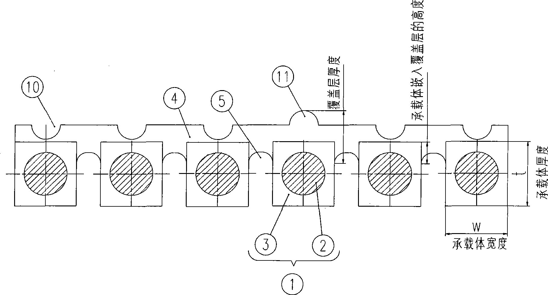
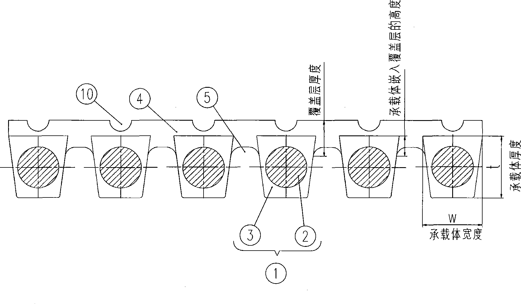
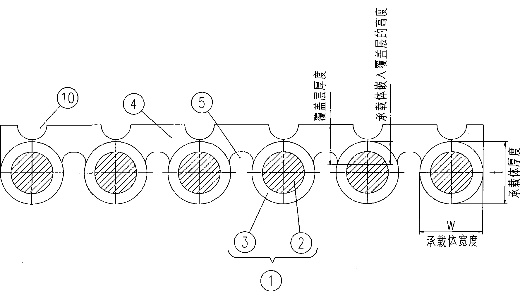
[0021] Such as figure 1 As shown, in the first structure of the rope for the elevator device, the rope is composed of six carriers 1 and one covering layer 4 . The carrier 1 is composed of a carrier core 2 and an enclosure 3 . The carriers 1 are arranged at a certain interval, and the covering layer 4 and the carriers 1 are connected together. The inclusion 3 and the covering layer are made of non-metallic materials. The carrier body 1 has the dimensions of a width w and a thickness t measured in the bending direction, wherein the ratio of the thickness t to the width w≧1. The carrier body 1 is partially embedded in the cover layer 4 . Since the thickness of the covering layer 4 is smaller than that of the supporting bodies 1 , the covering layer 4 can be designed to enable relative displacement between the supporting bodies 1 in the longitudinal direction. Since a plurality of bearing bodies 1 are partially embedded in the cover layer 4, the rope has better torsional flex...


PUM

PropertyMeasurementUnit
Optical diameteraaaaaaaaaa
Diameteraaaaaaaaaa

Abstract

The invention discloses an elevator rope, which comprises a plurality of supporting bodies and a coating layer, wherein the plurality of the supporting bodies are partially embedded into the coating layer; the adjacent supporting bodies are arranged according to certain spacing; each supporting body comprises a bearing core thread and a nonmetallic inclusion for enwrapping the bearing core thread; the supporting bodies are provided with the width w and the thickness t which is measured in the bending direction, and the ratio of the thickness t to the width w is more than or equal to 1; the coating layer is made of nonmetallic materials and connected with the supporting bodies; and the design of the coating layer can make the supporting bodies carry out relative displacement in the longitudinal direction. The invention also discloses a traction pulley and an elevator device which adopt the elevator rope. The elevator rope has good twisting flexibility and bending flexibility, long service life, simple and reliable manufacture and low cost, and an elevator system is more flexibly arranged.

Description

technical field [0001] The invention relates to a rope and a traction sheave for an elevator installation. The invention also relates to an elevator installation using said rope and traction sheave. Background technique [0002] In the elevator device driven by the traditional traction pulley, the stressed member is a steel wire rope. There are certain restrictions on the use of wire ropes, such as the limitation of the traction force between the wire rope and the traction pulley, the requirements on the bending performance and fatigue performance of the wire rope. Due to the limitation of traction, in order to increase the traction, it is often necessary to increase the wrap angle between the wire rope and the traction pulley, or slot the traction pulley, which will reduce the life of the wire rope. At the same time, due to the requirements of the bending performance and fatigue performance of the wire rope, the minimum diameter of the wire rope is 8mm (GB7588-2003 standa...

Claims


Application Information

Patent Timeline
IPC IPC(8): B66B11/04F16G9/00
Inventor 周双林甘靖戈王水来
Owner SHANGHAI MITSUBISHI ELEVATOR CO LTD
Learn More