Load-bearing member of elevator and elevator apparatus

A force-bearing component and elevator technology, applied in the field of force-bearing components, can solve problems such as high hardness, difficulty in pulling force components, and affecting the life of inclusions

Active Publication Date: 2009-03-18
SHANGHAI MITSUBISHI ELEVATOR CO LTD
View PDF1 Cites 3 Cited by
  • Summary
  • Abstract
  • Description
  • Claims
  • Application Information

AI Technical Summary

Problems solved by technology

It is for this reason that the flexibility of the tension member is greatly reduced
At the same time, due to the high hardness of the material of the inclusion, the friction coefficient between the inclusion and the traction pulley will also decrease, so that a better traction capacity cannot be achieved
Furthermore, due to the integration of the inclusions, the arrangement of the tension members can only be arranged in parallel with the traction pulley and the guide wheel, otherwise relatively large internal stress will be generated in the inclusions of the tension members, thereby accelerating the wear of the inclusions of the tension members, making the The life of the tension member is reduced; in addition, due to the integration of the inclusions, the distance between adjacent load-bearing core wires cannot be well guaranteed during processing, and it is possible that adjacent load-bearing core wires will contact, so that when the tension member is stressed, the relative The contacting load-bearing core wires will wear each other, which will cause the load-bearing core wire to break, reduce the strength of the tension member, and may accelerate the wear of the inclusions, affecting the service life of the tension member. It is difficult to design tension members with different strengths at the same time
At the same time, because the inclusions are integrated and the inclusions are rubber materials, the inclusions will generate heat after being stressed, and the heat cannot be dissipated well, which will affect the life of the inclusions and reduce the life of the tension member; furthermore, the inclusions The integration of the load-bearing core wire will cause the breakage of the load-bearing core wire to be difficult to distinguish, and can only be detected by special equipment

Method used


Image

  • Load-bearing member of elevator and elevator apparatus
  • Load-bearing member of elevator and elevator apparatus
  • Load-bearing member of elevator and elevator apparatus

Examples


Embodiment 1

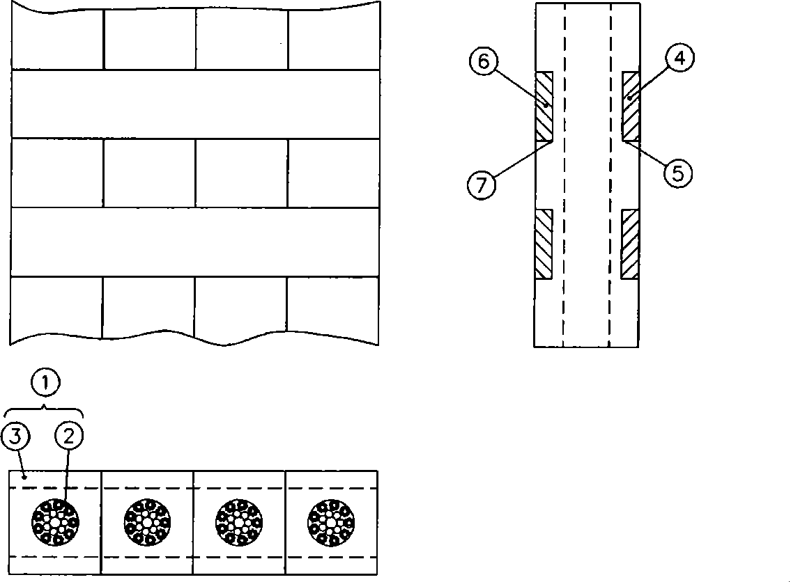
[0022] Such as figure 1 As shown, the force-bearing member includes four bearing bodies 1, and the four bearing bodies 1 are arranged adjacent to each other, and the side end surfaces between two adjacent bearing bodies 1 are not adhered. The ratio of the width dimension to the thickness dimension of the carrier is ≤1. Each carrier 1 is composed of an inclusion 3 and a carrying core 2 , and the carrying core 2 is wrapped inside the inclusion 3 . There are 9 strands on the periphery of each load-bearing core wire 2, and a strand in the center. Each strand of each carrying core wire 2 is formed by parallel twisting of a plurality of metal core wires. In this way, the contact between the metal core wires of each strand is line contact, so that the contact stress between the metal core wires is reduced, and the carrying core wire 2 can maintain a good shape. In order to improve the bending fatigue strength of the load-bearing core wire 2, the metal core wire is required to be r...

Embodiment 2

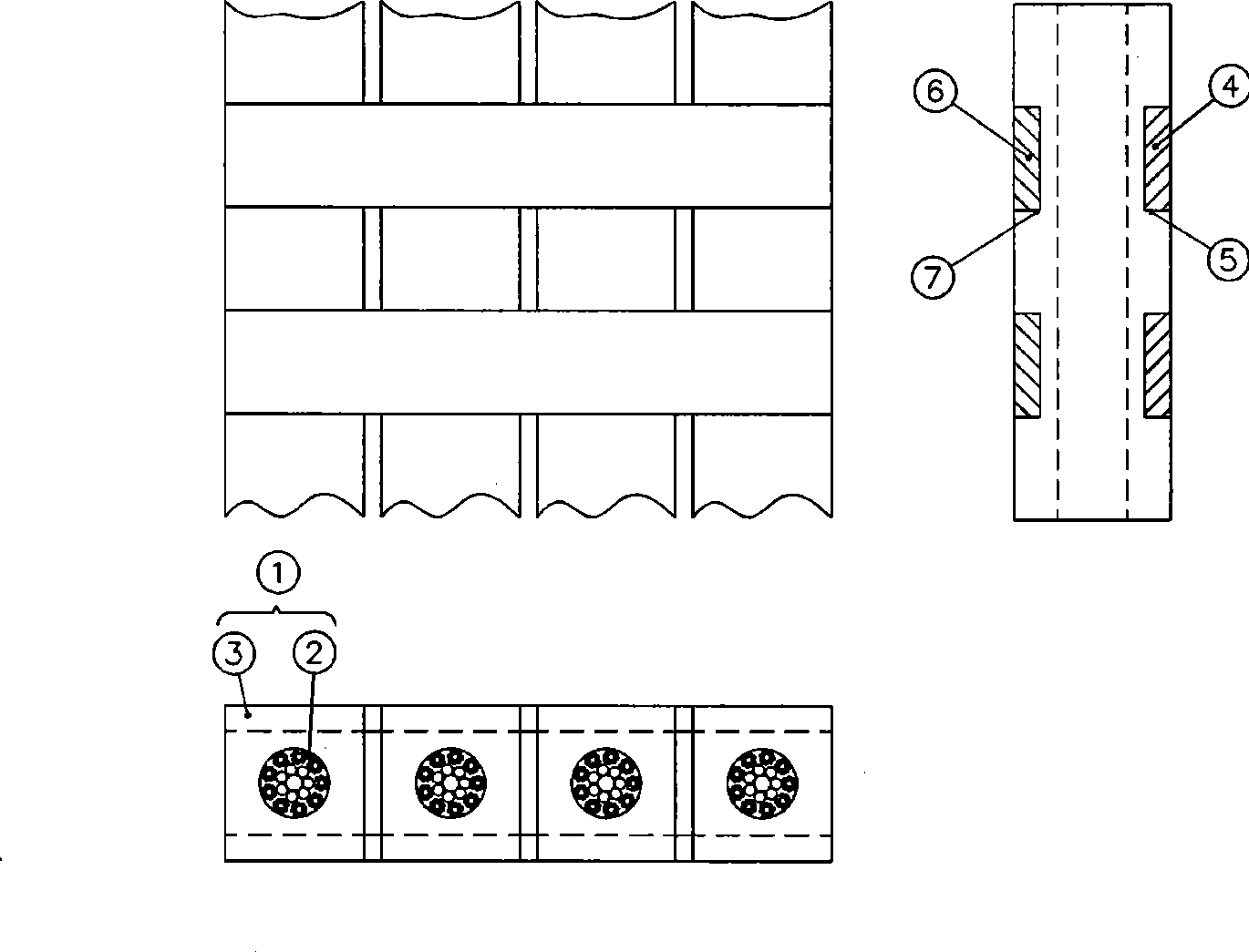
[0034] Such as figure 2 shown. The difference between this embodiment and the first embodiment is that there is a certain gap between adjacent carriers 1 . The advantage of doing this is that the heat generated by the elongation of the bearing body 1 under external force can be discharged through the gap between adjacent bearing bodies 1 faster, which will effectively improve the service life of the stressed member.

Embodiment 3

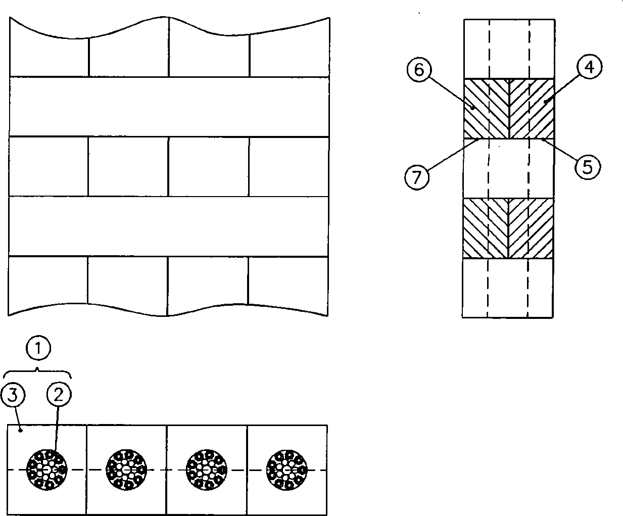
[0036] Such as image 3 shown. The difference between this embodiment and the first embodiment is that the grooves 5 and 7 communicate with each other. At the grooves 5 and 7 , the cladding layer 4 or the cladding layer 6 is firmly connected with the carrying core wire 2 and the inclusion 3 . There is no adhesion between adjacent carriers 1 .


PUM

PropertyMeasurementUnit
diameteraaaaaaaaaa
strengthaaaaaaaaaa
diameteraaaaaaaaaa

Abstract

The invention discloses a force-bearing component for elevators, which comprises a plurality of adjacent bearing bodies. Each bearing body consists of a wrapping body and a bearing core wire, wherein the bearing core wire is wrapped in the wrapping body; the upper and lower surfaces of the wrapping body along the longitudinal direction are transversely and correspondingly provided with a plurality of grooves; coating layers are arranged in the grooves, and are fixedly connected with the wrapping bodies, so as to connect the bearing bodies together; the thickness size of each coating layer is generally equal to the depth of the grooves on the upper and lower surfaces of the wrapping body; and the width size of each coating layer is more than the thickness size thereof at least. The invention also discloses an elevator device adopting the force-bearing component. The force-bearing component has the advantages of better flexibility and dragging capability, and longer service life. In addition, the force-bearing component is simple to process, and the fracture situation of the bearing core wire can be distinguished through appearance.

Description

technical field [0001] The invention relates to a force-bearing member for traction elevators. The present invention also relates to an elevator device using the force-bearing member. Background technique [0002] In the elevator device driven by the traditional traction pulley, the stressed member is a steel wire rope. There are certain restrictions on the use of wire ropes, such as the limitation of the traction force between the wire rope and the traction pulley, the requirements on the bending performance and fatigue performance of the wire rope. Due to the limitation of traction, in order to increase the traction, it is often necessary to increase the wrap angle between the wire rope and the traction pulley, or slot the traction pulley, which will reduce the life of the wire rope. At the same time, due to the requirements of the bending performance and fatigue performance of the wire rope, the minimum diameter of the wire rope is 8mm (GB7588-2003 standard), and the di...

Claims


Application Information

Patent Timeline
Patent Type & Authority Applications(China)
IPC IPC(8): D07B1/22D07B1/16B66B9/00B66B11/08
Inventor 周双林
Owner SHANGHAI MITSUBISHI ELEVATOR CO LTD
Why Eureka
Try Eureka